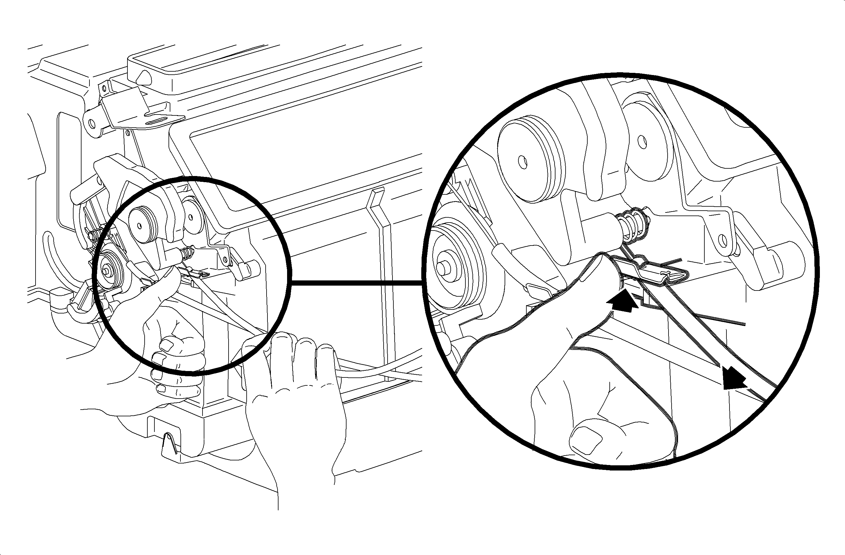

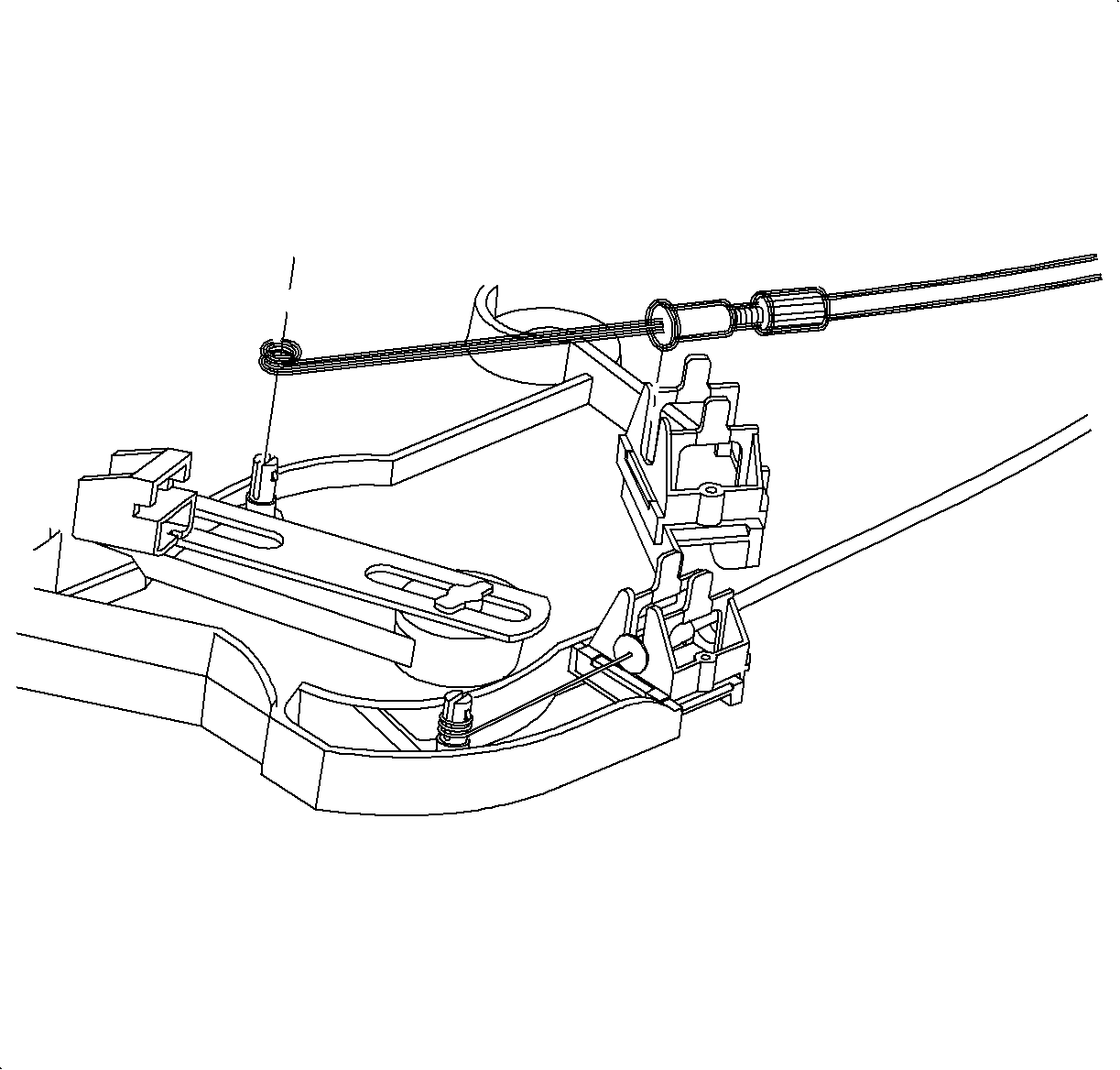
- Rotate mode cam fully counterclockwise.
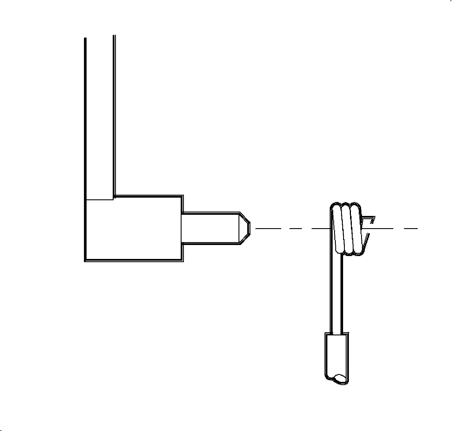
- Install mode cable with wire eyelet wrap as shown.
Important
Do not install mode cable housing into retainer clip at this time.
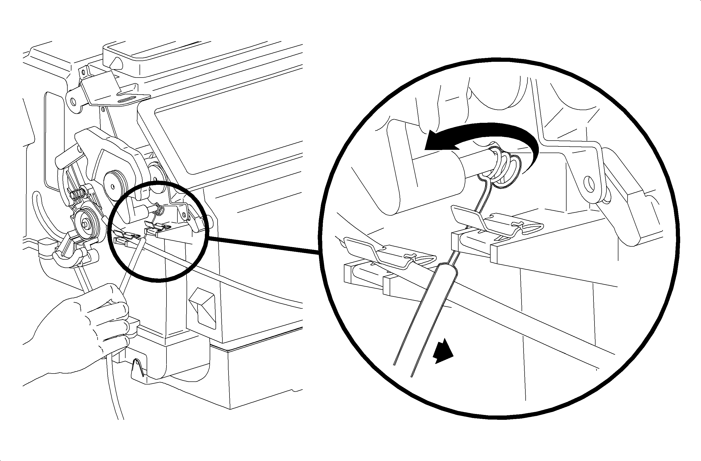
- Install mode cable eyelet between mode cam pin and module case and rotate onto
mode cam pin.
- Install mode cable over HVAC control pin.
- Install mode cable housing into channel and push down to lock into place.
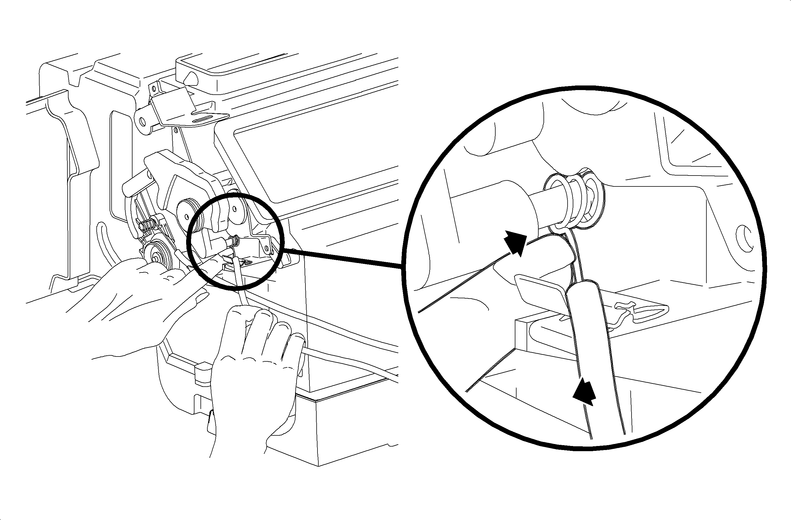
- Place HVAC control mode lever completely to the
right - defrost position.
- Verify that mode cam is still in full counterclockwise
position.
- Press mode cable housing in firmly into retainer clip to lock.
- Move HVAC control mode lever through modes to verify proper installation.
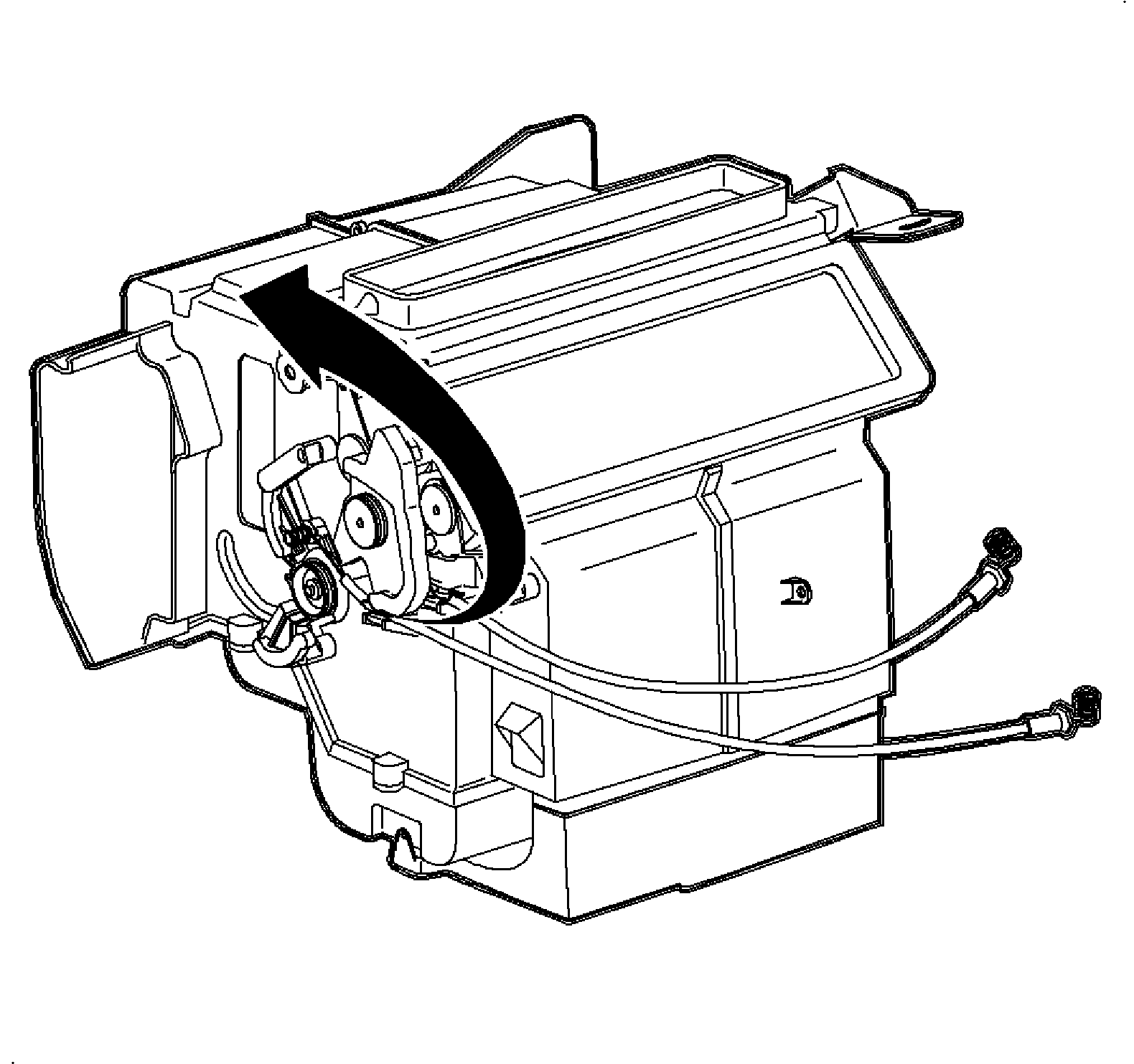
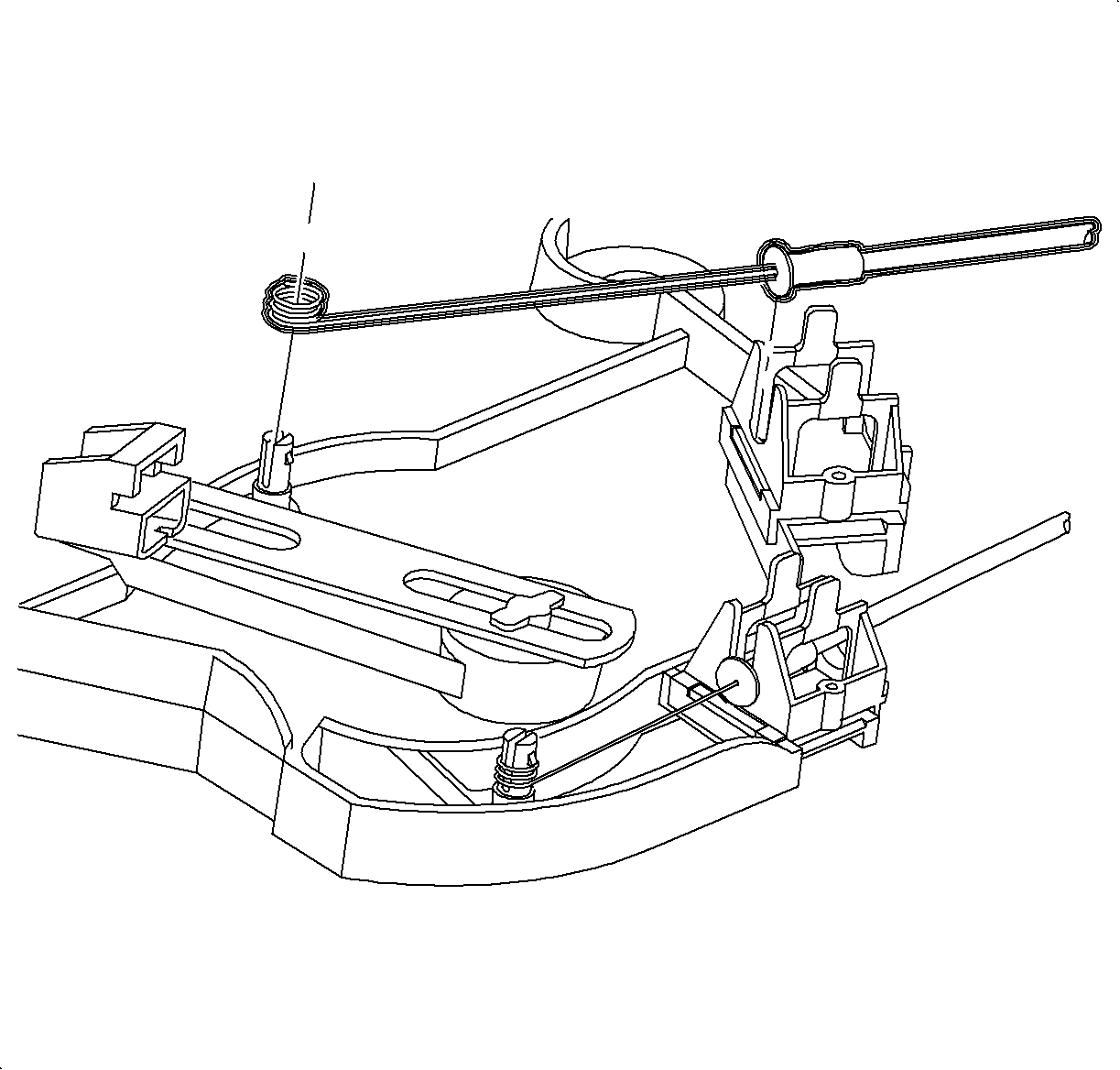
- Install the mode cable over the pin.
- Install the mode cable housing into the channel and push down to lock.
Important
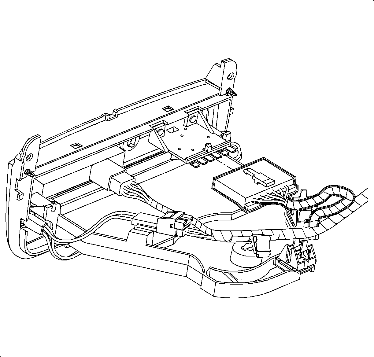
Make sure the wiring harnesses do not interfere with control lever movement.
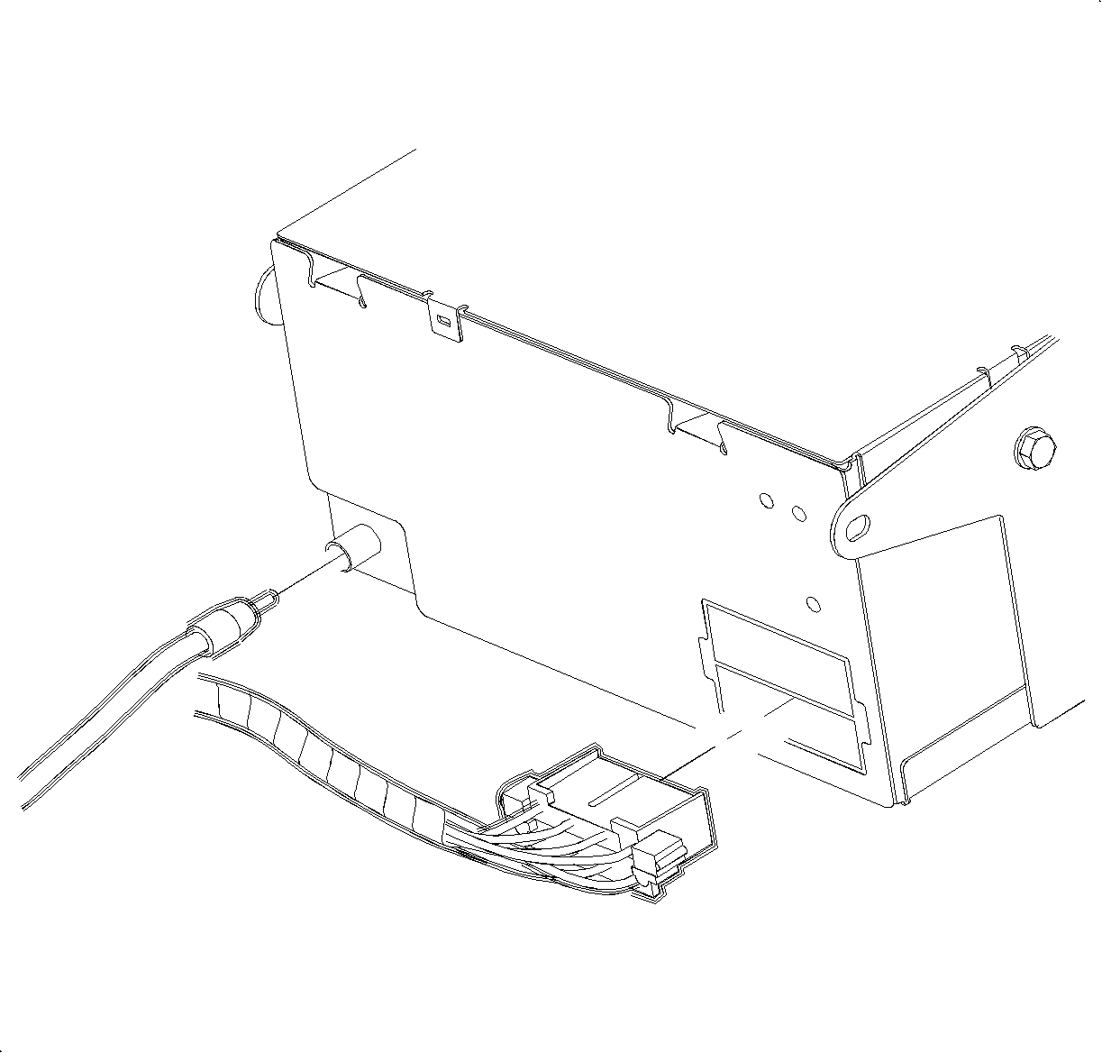
- Connect the blower switch, A/C-Recirc and lighting electrical connectors.
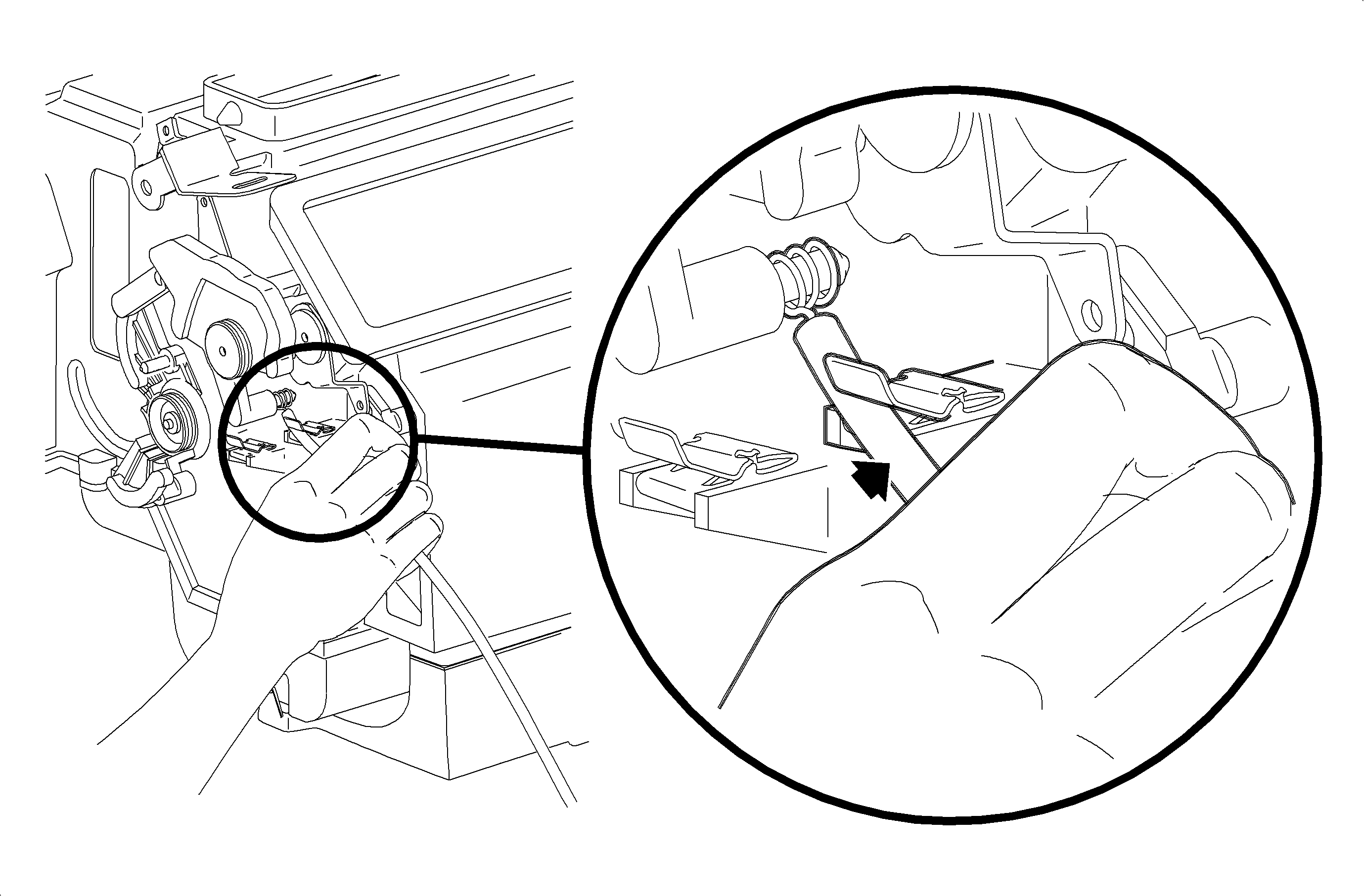
- Connect the electrical connector and antenna
to radio.
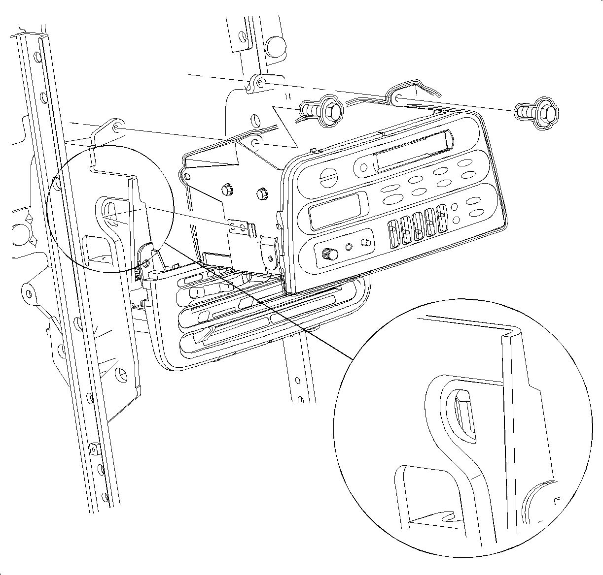
- Install the radio.
Important
Make sure the spring clips are seated in D-holes on both sides.
- Install and tighten the screws.
TightenTighten to 2.5 N·m (22 lbs in)
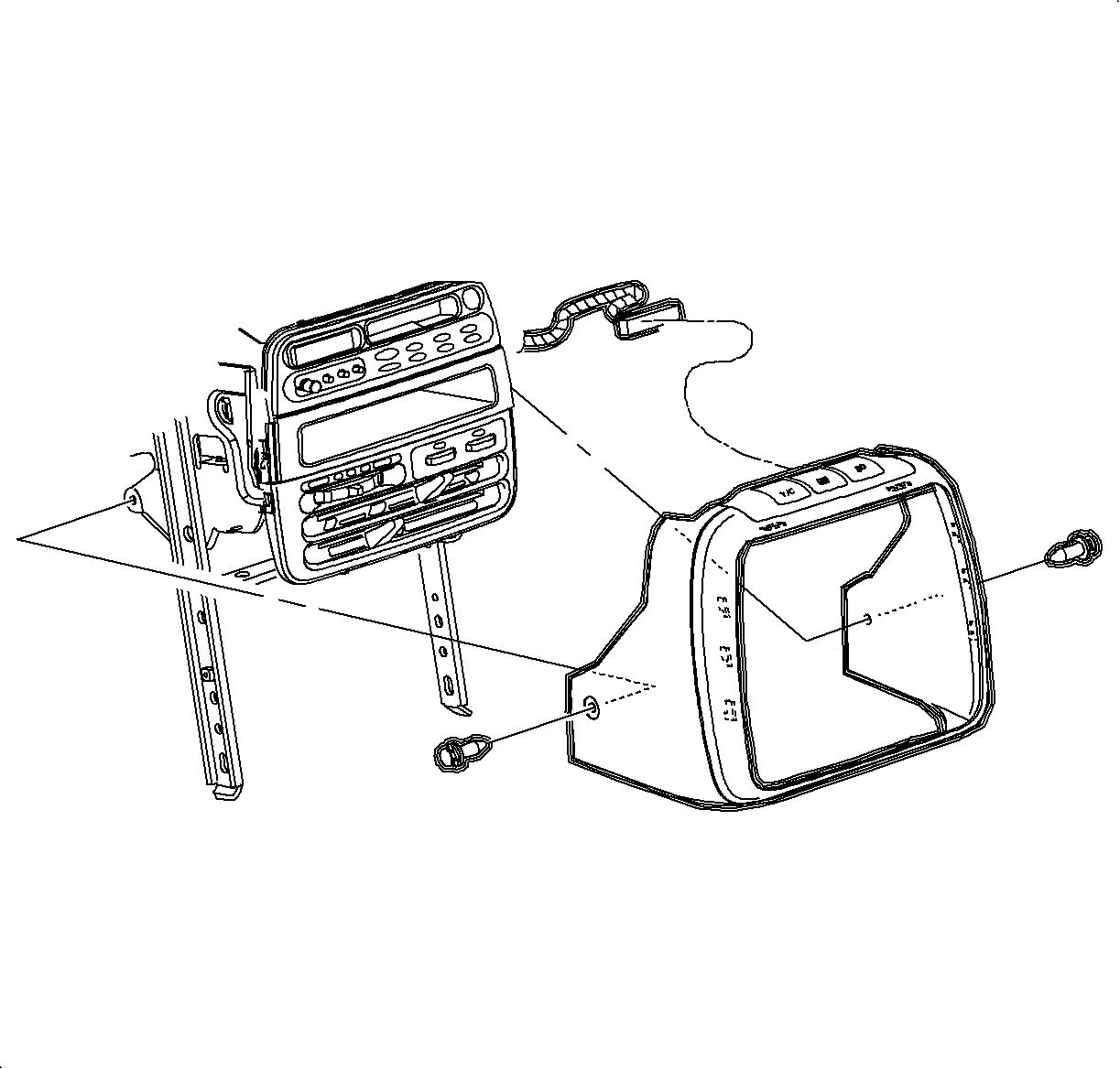
- Connect the traction control/fog lamp/rear defog
electrical connector, if equipped.
- Install the radio/HVAC controller cover. Push in at the clip locations.
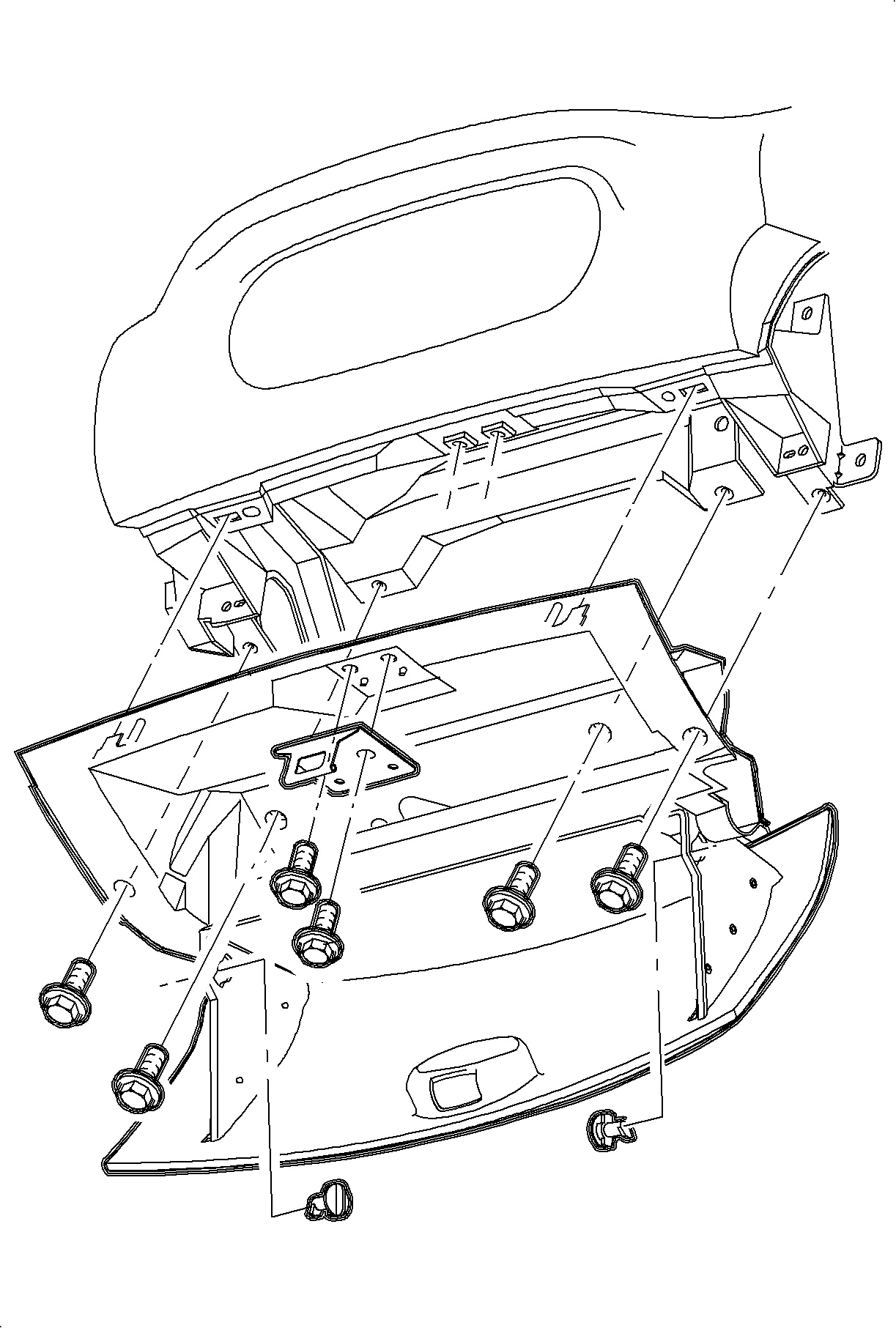
- Install glove box and snap in at clip locations.
- Install and torque screws.
TightenTighten to 2.2 N·m (20 lbs in)
- Install glove box door stops.
- Adjust striker as necessary.