
- Assemble the timing chain, sprockets, guides and tensioner:
- Verify that the crankshaft is positioned 90 degrees clockwise past
top dead center (TDC), viewed from the accessory drive belt end of the crankshaft.
The crankshaft key way sprocket timing mark must be aligned with the cylinder block
main bearing cap split line to prevent piston and valve damage.
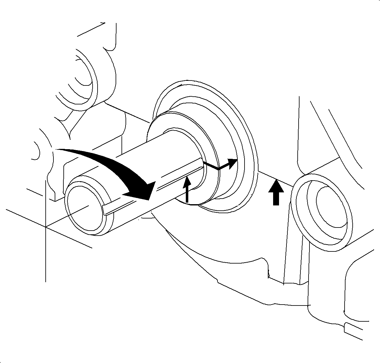
- If required, bring the camshaft up to number one top dead center (TDC). The
camshaft can be verified at TDC by loosely installing the sprocket and rotating the
sprocket until the timing pin (3/16 in drill) can be installed. The dowel
pin in the camshaft will be located at the 12 o'clock position. Wrench flats
21 mm (7/8 in) are installed on the camshaft to assist with rotating
the cam slightly or by installing the sprocket and bolt. Only turn the camshaft clockwise
to prevent intake and exhaust valve damage. The camshaft sprocket and bolt will have
to be installed if the camshaft must be rotated more than a few degrees.
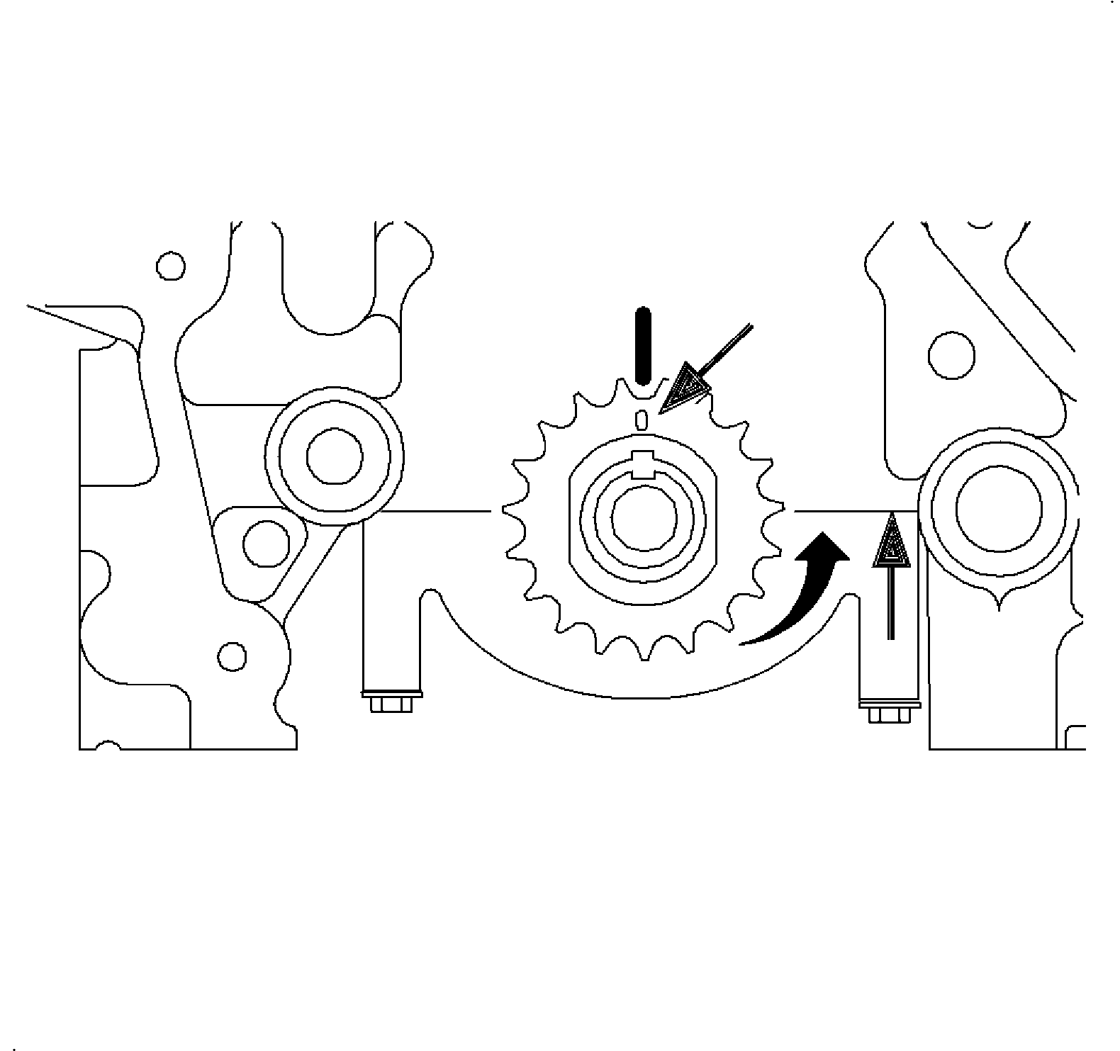
- Rotate the crankshaft 90 degrees counterclockwise, (viewed from accessory
drive belt end of crankshaft, up to number one TDC. The crankshaft sprocket timing
mark will align with cylinder block timing mark.
Important
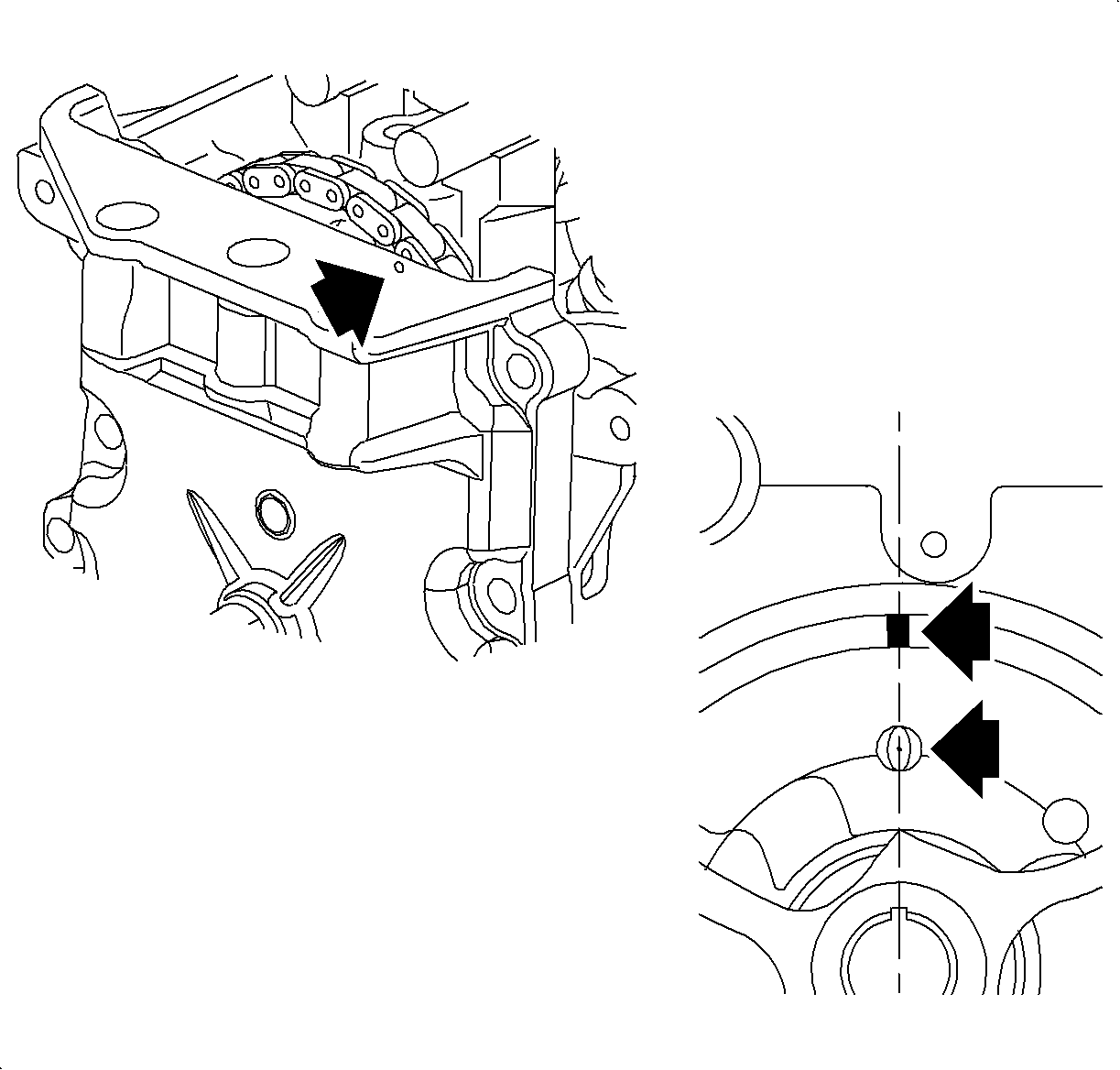
- One silver link plate aligns with the pip mark on the camshaft sprocket
and the other aligns with the crankshaft sprocket tooth that is pointed directly
downward at the 6 o'clock position. The pip mark on the crankshaft sprocket
must be aligned with the timing mark on the cylinder block.
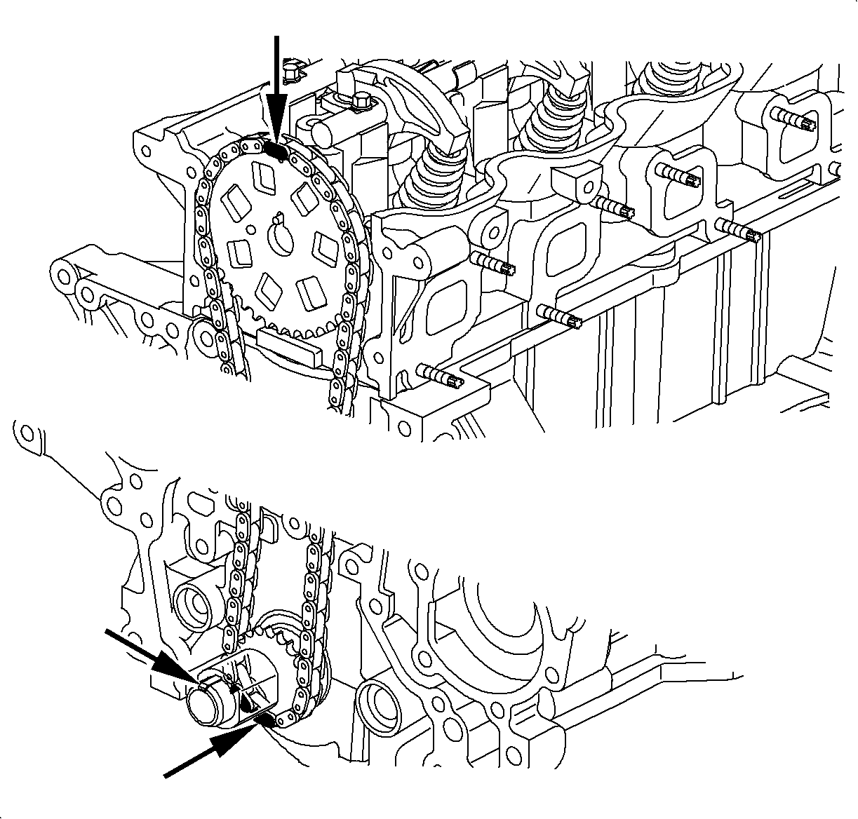
- Excess slack in the chain must be kept to the tensioner side of the cylinder
block.
- Place the timing chain over the camshaft sprocket, and under the crankshaft
sprocket. Slide the camshaft sprocket onto the camshaft. The letters FRT on the camshaft
sprocket must face forward away from the cylinder head.
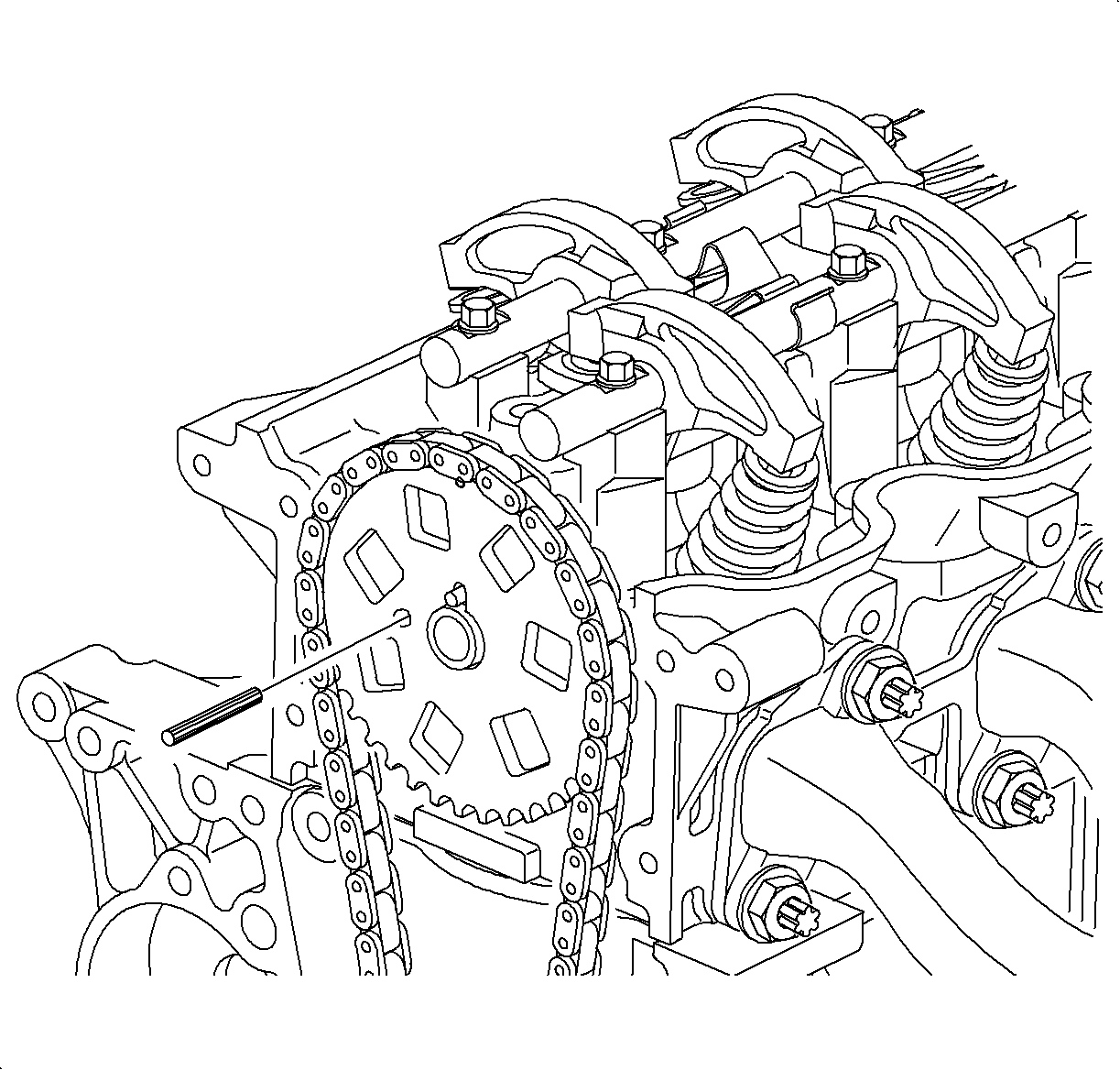
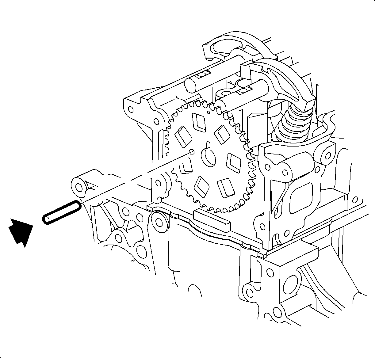
- Install the camshaft sprocket timing pin (3/16 in drill).
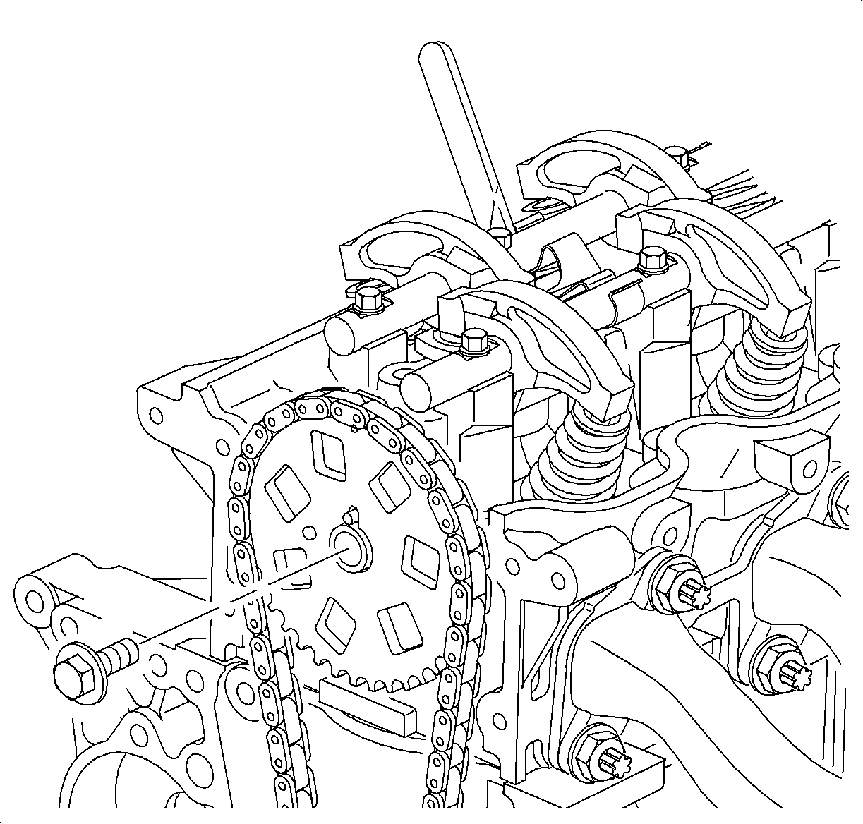
Notice
Do not torque the camshaft retaining bolts against the 3/16 in. timing
pins as it will damage the cylinder head.
- Install the camshaft washer and bolt. Wrench flats 22 mm
(7/8 in) are located on the cam to hold it.
TightenTighten the camshaft sprockets-to-camshafts to 100 N·m (74 lb ft).
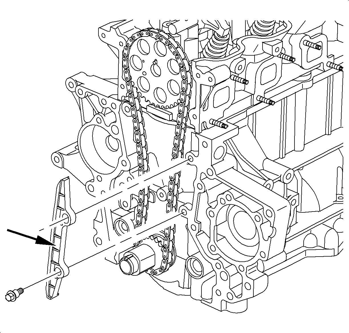
Important
The timing chain should be snug against the fixed guide.
- Install the fixed chain guide and check for clearance between the guide to cylinder
block and head. The guide must be installed with the word FRONT facing forward away
from the cylinder block.
TightenTighten the timing chain fixed block-to-head to 26 N·m (19 lb ft).
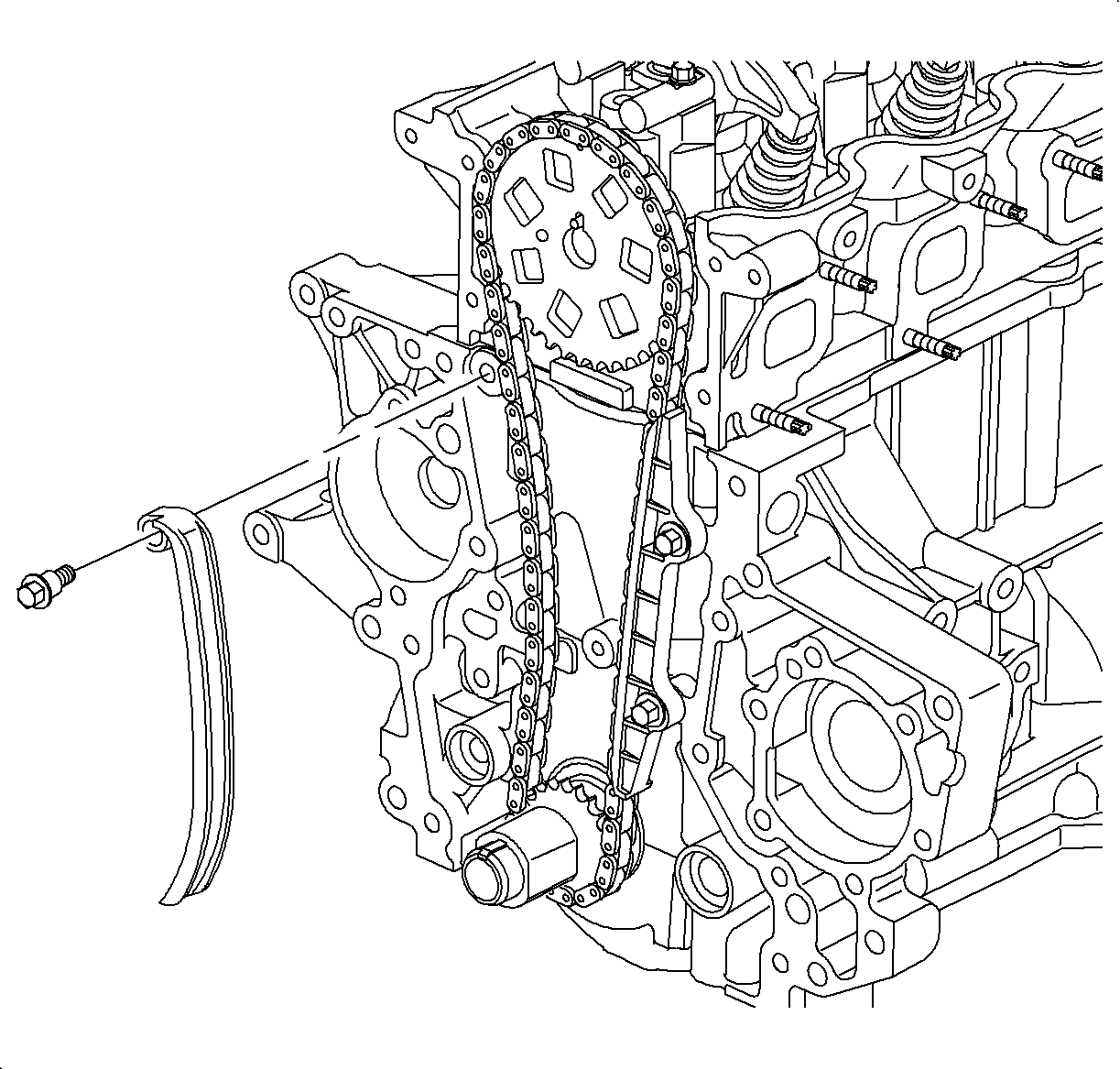
- Install the pivoting chain guide. Check for clearance between the block and
head. Torque the bolt and make sure the guide pivots freely.
TightenTighten the timing chain pivot guide-to-head to 26 N·m (19 lb ft).
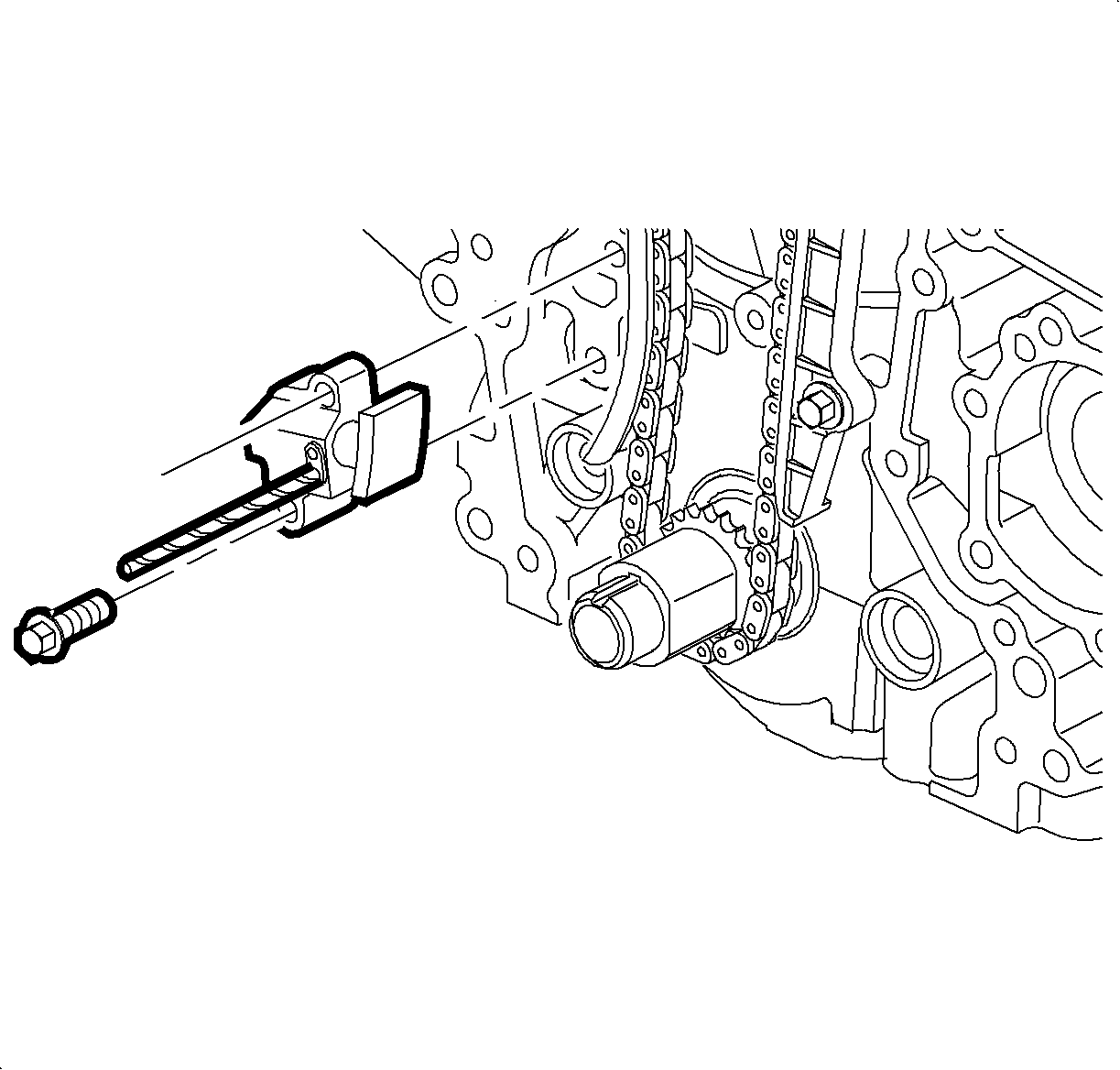
- Retract the tensioner plunger and pin the ratchet lever using a 3.18 mm
(1/8 in No 31) drill. Install the chain tensioner and torque
the two bolts. Remove the drill and allow the tensioner plunger to extend.
TightenTighten the timing chain tensioner-to-block 19 N·m (168 lb in).
- Verify all timing marks for accuracy. Remove the camshaft timing pins
4.77 mm (3/16 in) drill.
- Camshaft timing verification procedure with engine assembled (front cover on):
- Remove the rocker cover.
- Turn the crankshaft until the mark on the crankshaft pulley aligns with
the pip mark on the front cover.
Important
The camshaft sprocket timing pin hole is located below the front cover upper
gasket surface and cannot be used as a reference. It may be necessary to remove the
right-hand road wheel and splash shield to observe timing marks on front cover and
crankshaft pulley.
- The letters FRT on the camshaft sprocket should align with the upper gasket
surface of the front cover and only the pip mark on the cam sprocket should be at
the 12 o'clock position. If the letters and pip mark don't align, rotate the
crankshaft an additional 360 degrees. If the letters FRT and pip mark
do not align, the crankshaft and camshaft are not timed.