
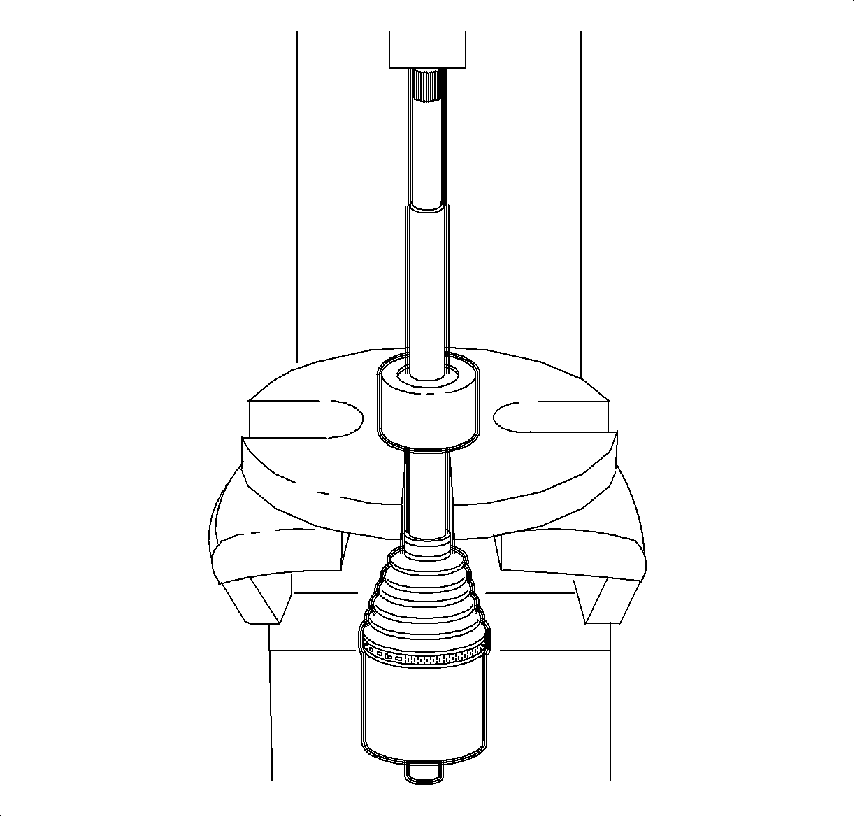
Use soft metal or wood in between vice jaws to protect the shaft.Important
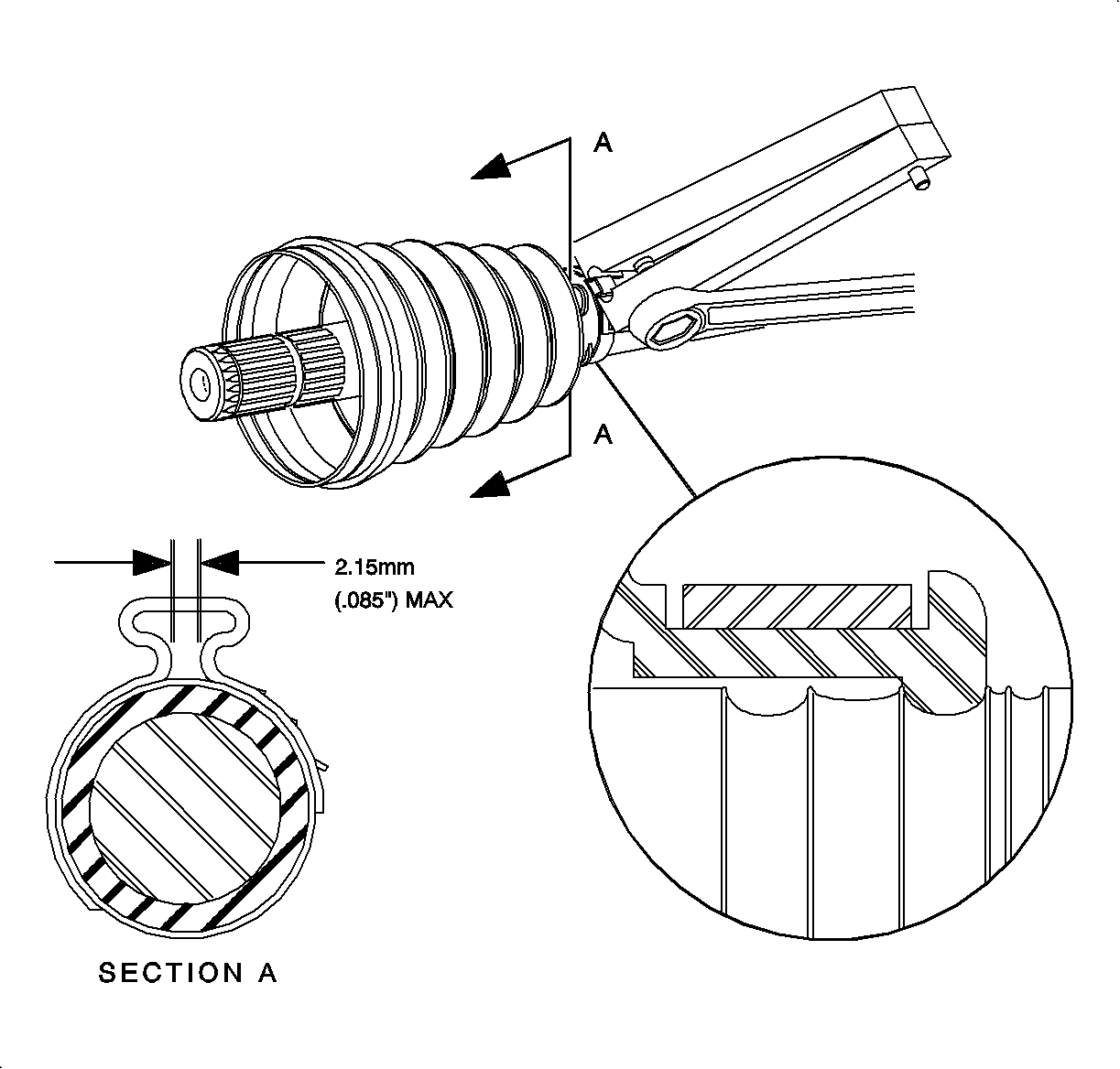
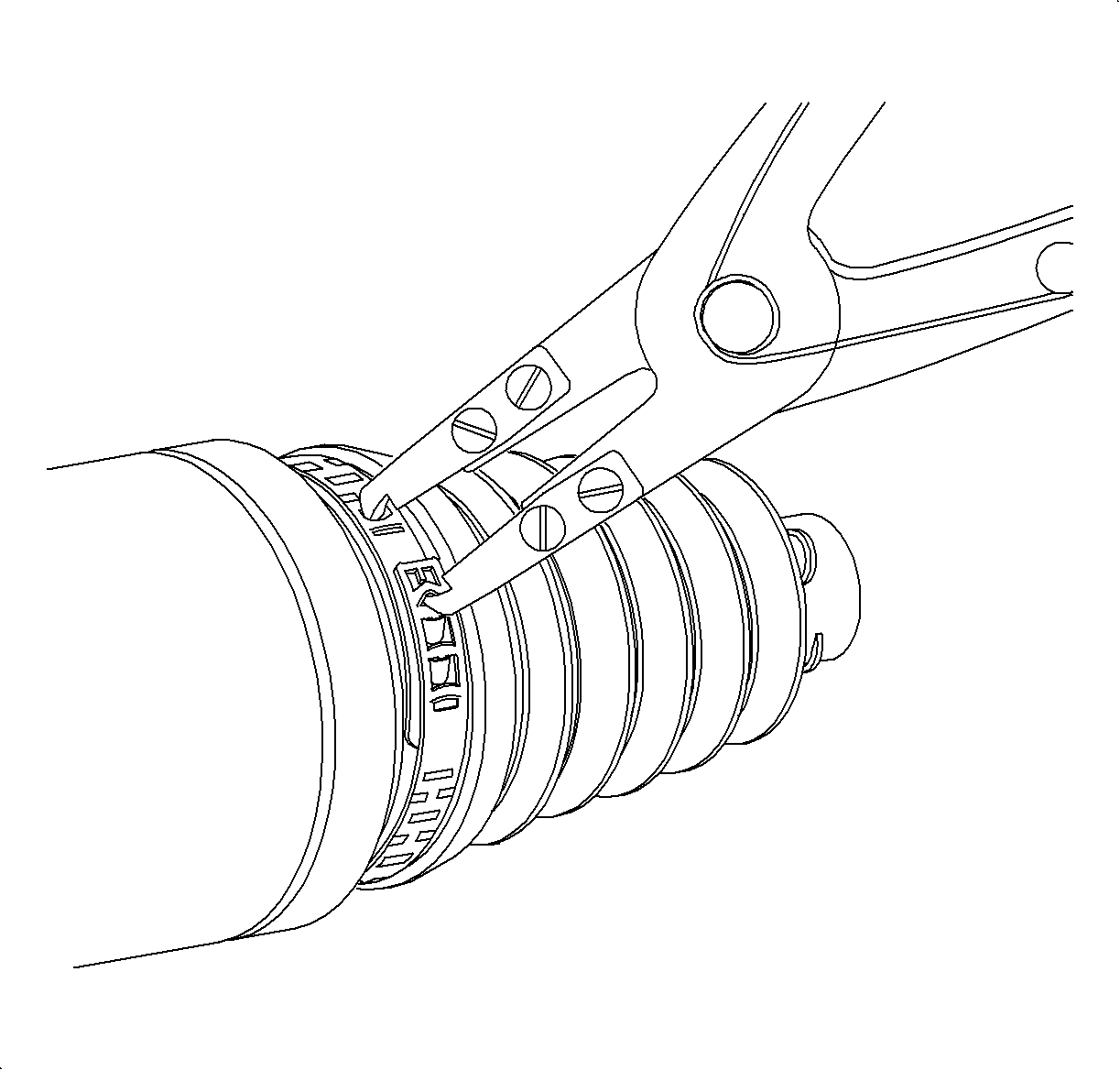
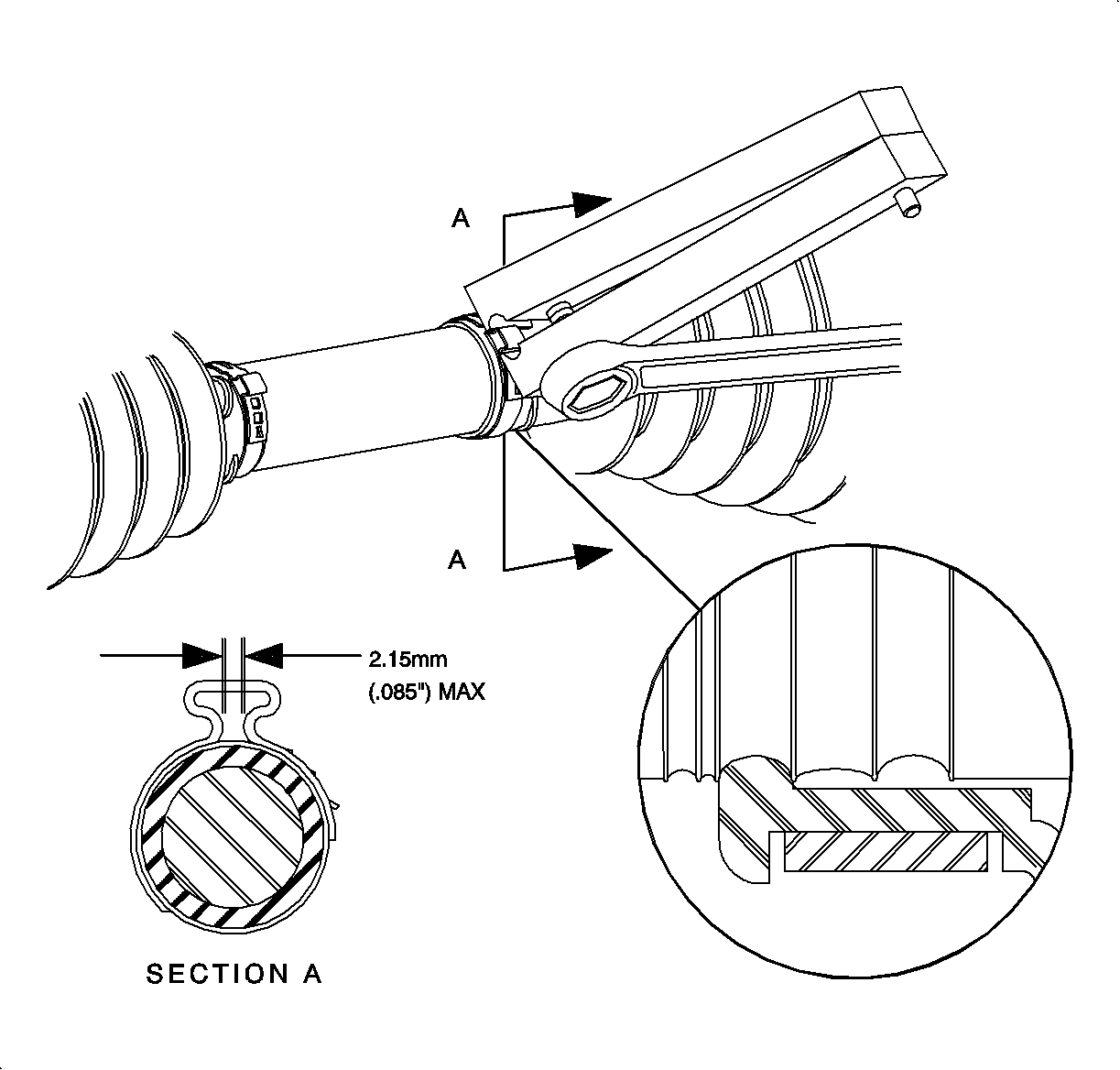
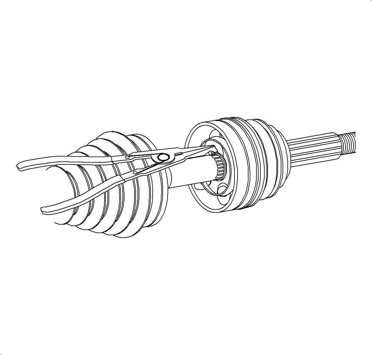
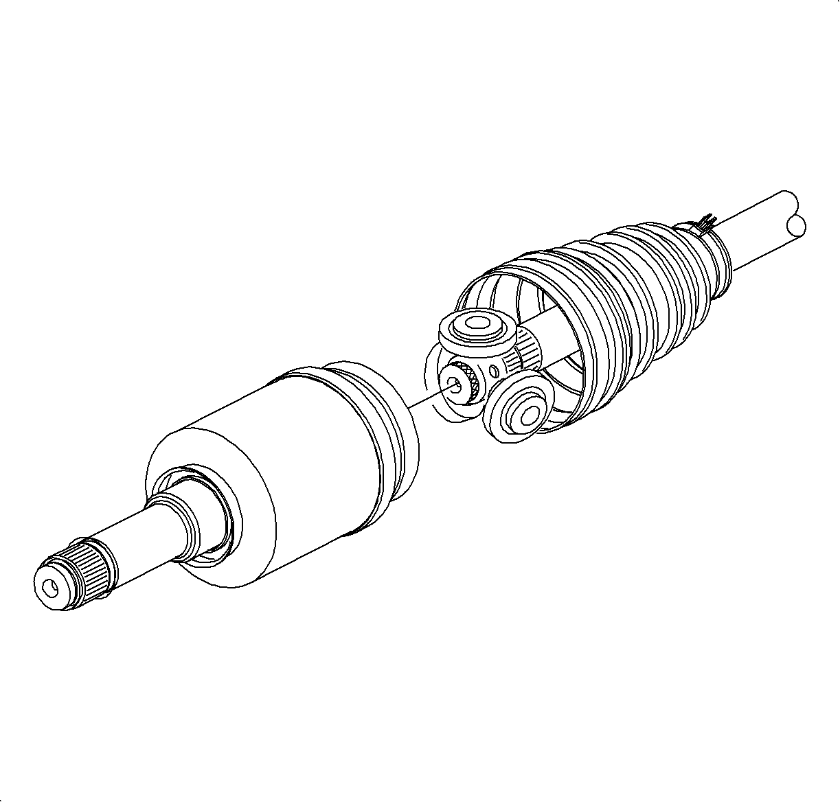
- Use a hammer and chisel or a flat-blade screw driver to disengage the outer band from the inner band at the retainer peg on both large and small boot clamps and discard the clamps.
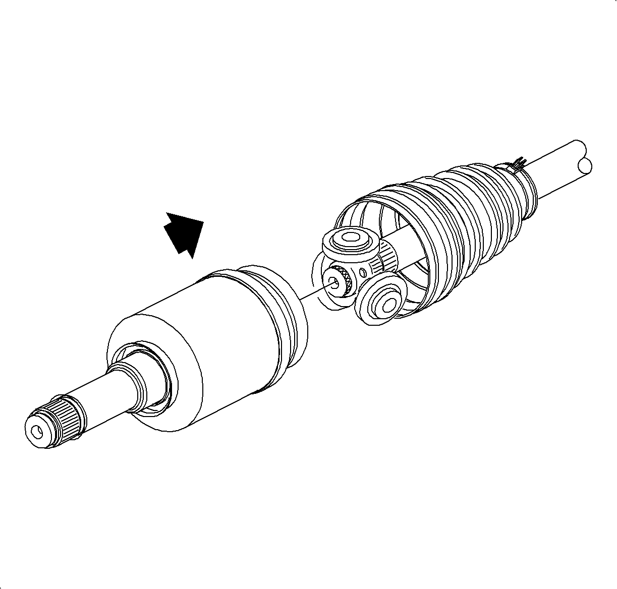
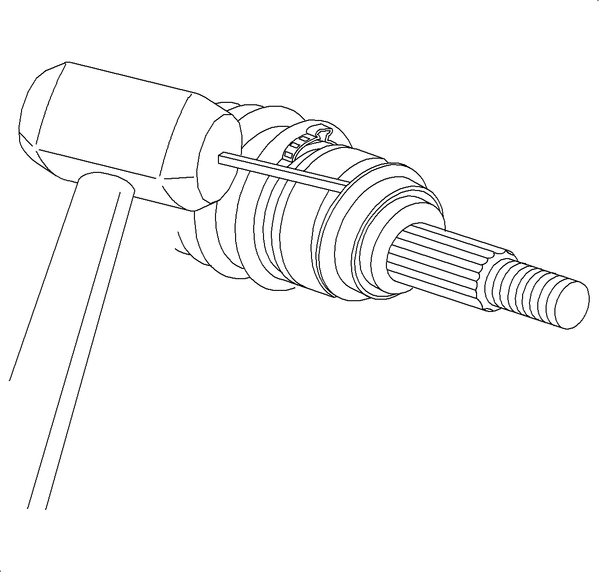
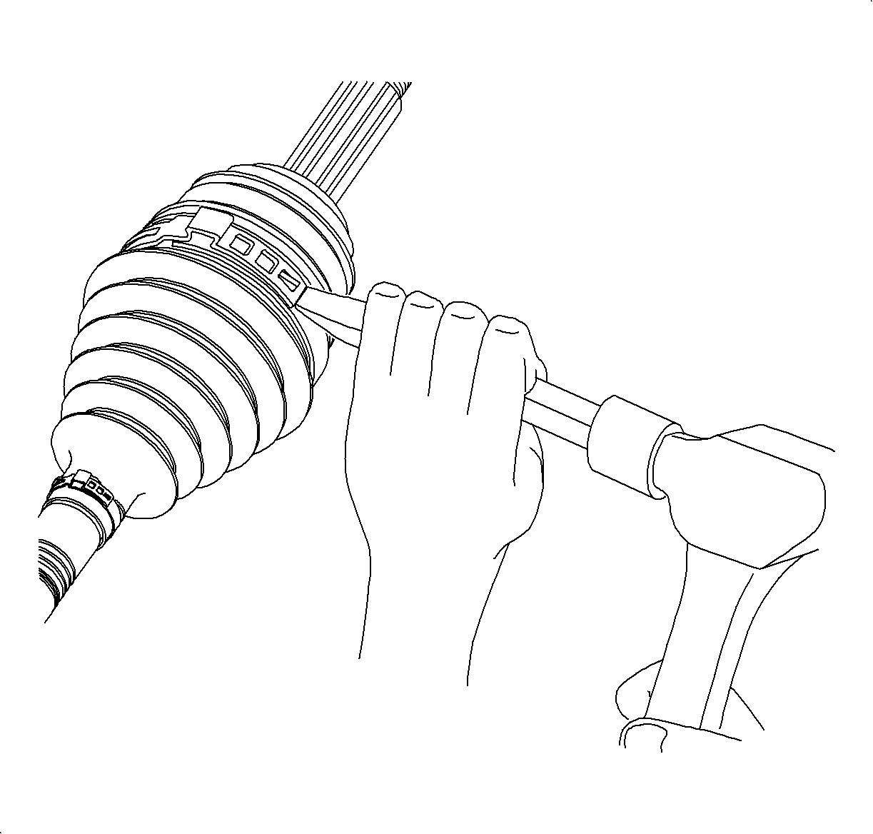
- Separate the joint boot from the CV joint race at the large diameter and slide the boot away from the joint along the axle shaft.
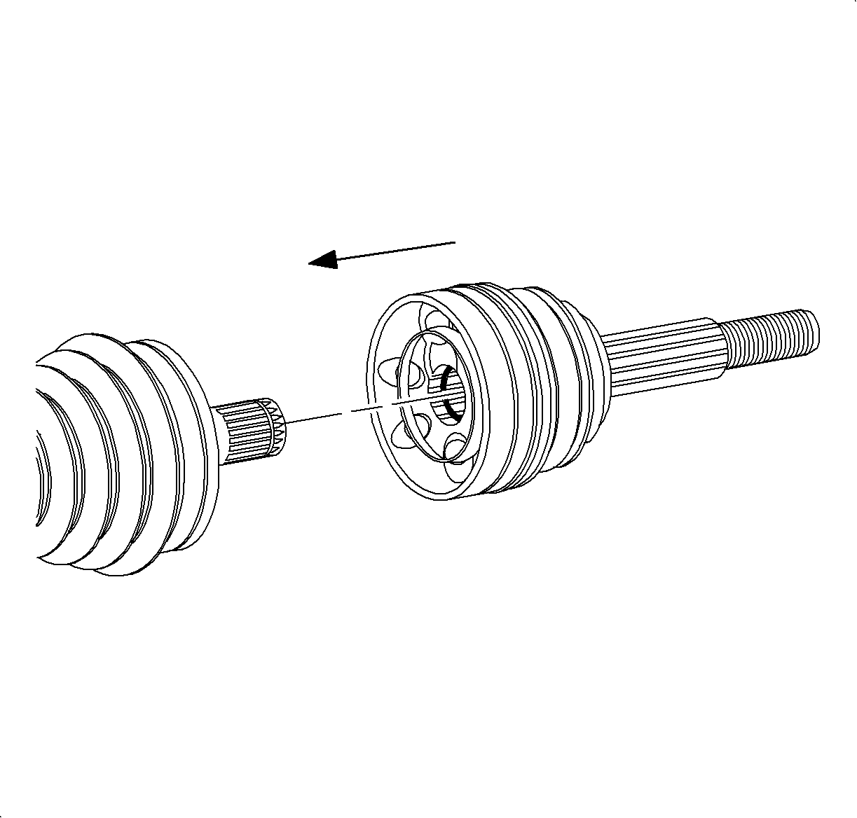
- Wipe excess grease from the face of the CV inner race.
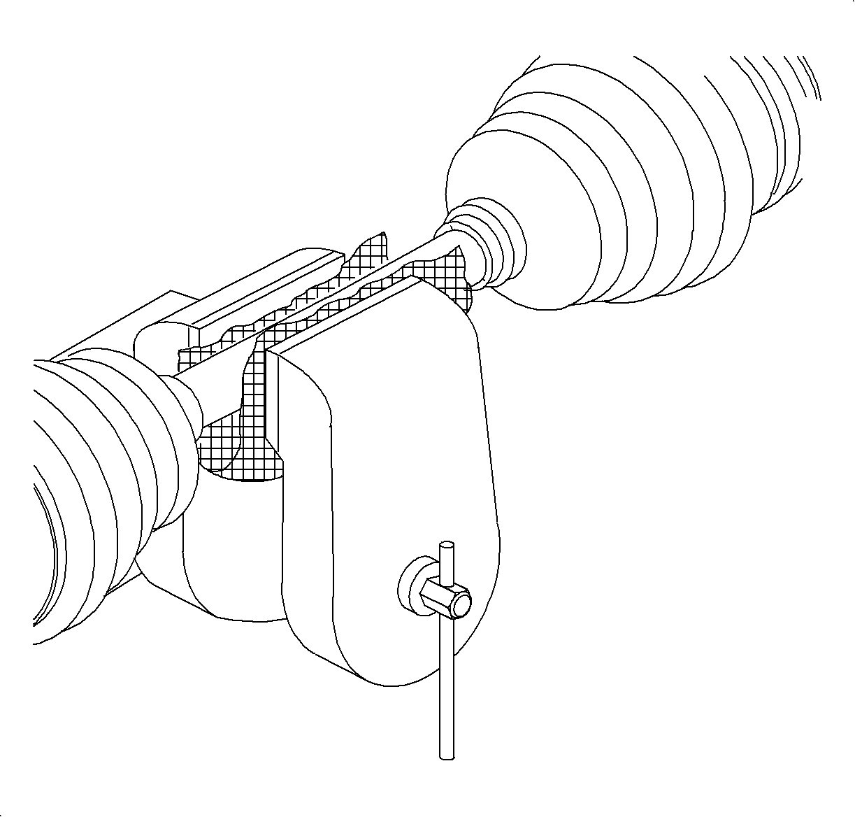
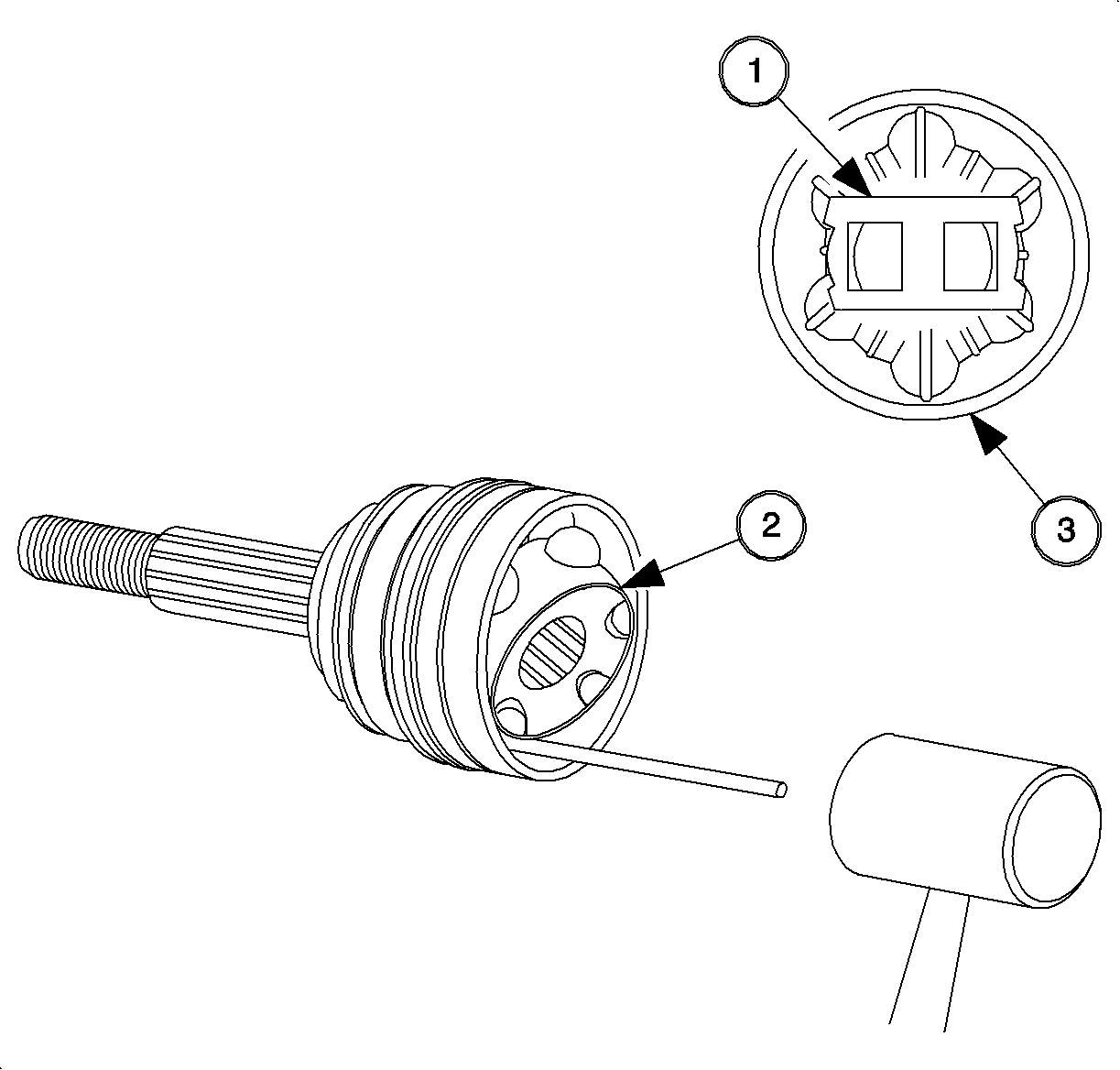
- Spread the ends on the race retaining ring with the SA9198C or equivalent, and remove the CV joint assembly from the axle shaft.
- Remove the boot from the axle shaft.
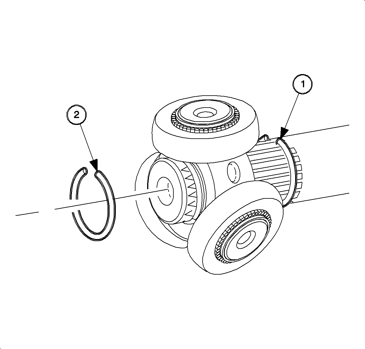
- Using a brass drift, gently tap on cage (1) until it is tilted enough to remove the first ball.
- Remove the remaining balls in a similar manner.
- With all balls removed, pivot the cage and inner race (2) at 90 degrees to the center line of the outer race (3) with the cage windows aligned with the lands of the outer race, lift out the cage and the inner race.
- Rotate the inner race up and out of the cage.
- Thoroughly degrease all CV joint parts and allow them to dry prior to assembly.
- Inspect the parts for unusual wear, cracks and other damage. Replace the joint assembly if needed.
- Put a light coat of recommended grease on the inner and outer race grooves.
- Insert and rotate the inner race into the cage.
- Install the cage and the inner race into the outer race with the windows of the cage aligned with the lines of the outer race.
- Install the balls using a brass drift to gently rotate and position the cage and the inner race.
- If removed, install the race retaining ring into the inner race.
- Pack the assembled joint with grease provided in the service kit. The amount of grease supplied with service kits has been pre-measured for each application.
- Cut the eared boot retaining clamp on the tri-pot boot with side cutters and discard.
- Remove the earless clamp, using a small-blade screwdriver and discard.
- Separate the boot from the tri-pot housing at the large diameter and slide the boot away from the joint along the axle shaft.
- Wipe excess grease from the face of the tri-pot spider and the inside of the tri-pot housing.
- Remove the tri-pot housing from the spider and shaft.
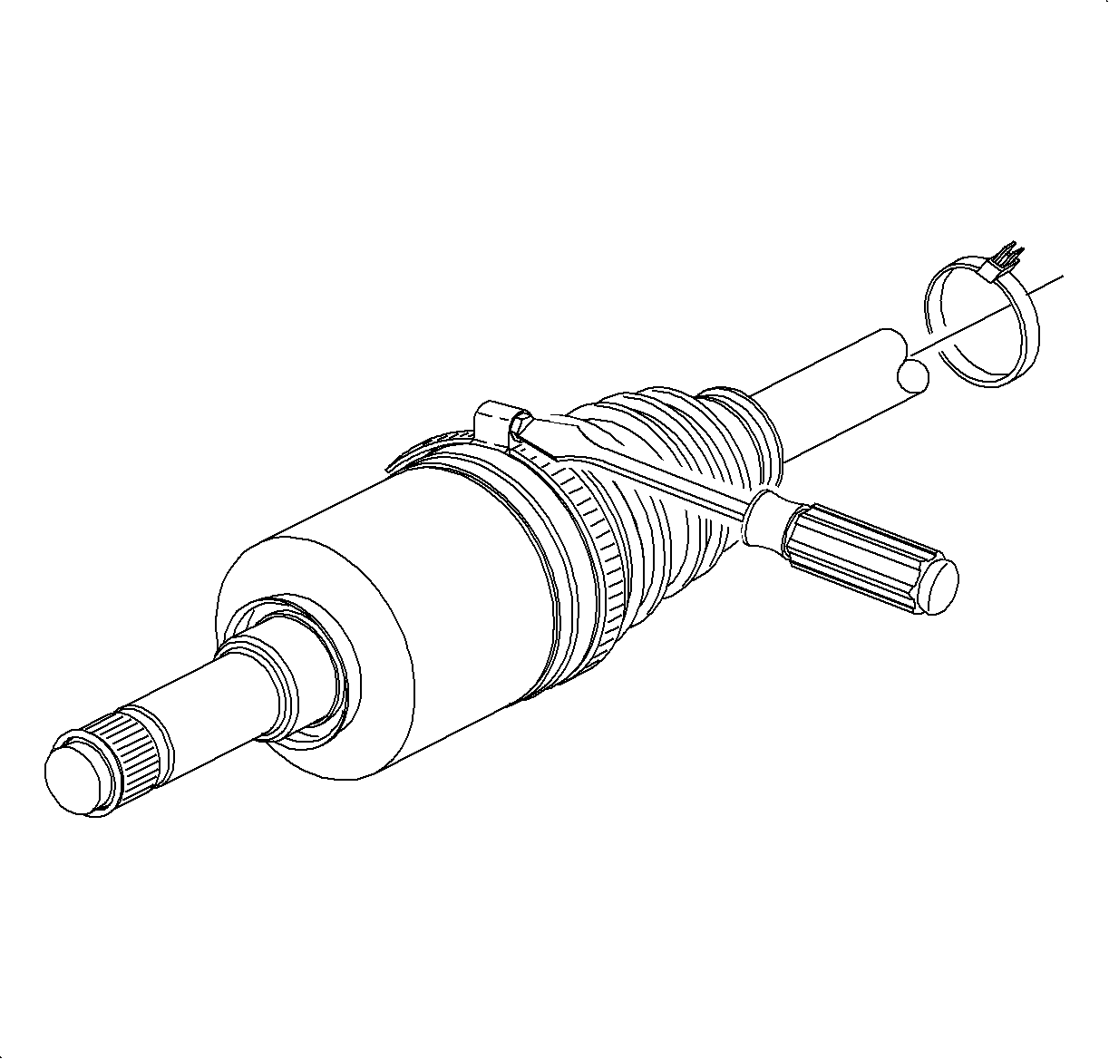
- Spread the spacer ring (1) with the SA9198C or equivalent , and slide the spacer ring and tri-pot spider back on the axle as shown.
- Remove the spider retaining ring (2) from the groove on the axle shaft and slide the spider assembly off of the shaft.
- Remove the boot from the axle shaft.
- Thoroughly degrease the housing and allow the housing to dry prior to assembly.
Handle the tri-pot spider assembly with care. Tri-pot balls and needle rollers
may separate from spider trunnions.Notice