
- Disconnect negative
battery cable.
Caution
Ensure that the vehicle is properly supported and squarely positioned.
To help avoid personal injury when a vehicle is on a hoist, provide additional support
for the vehicle on the opposite end from which the components are being removed.
- Raise vehicle on hoist.
- Remove front wheels and tires.
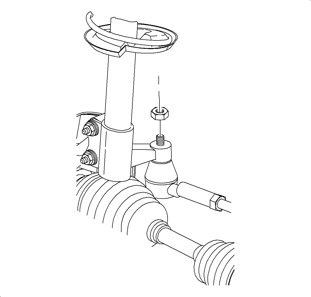
- Remove and discard
torque prevailing nut. A new nut will be required during assembly.
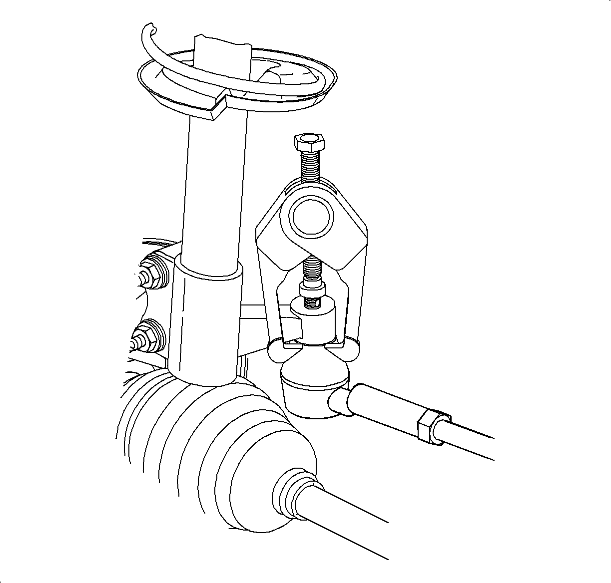
Notice
Do not attempt to separate the joint using a wedge-type tool because seal may
be damaged.
- Using
SA91100C
(or equivalent), remove tie rod ends from steering knuckle.
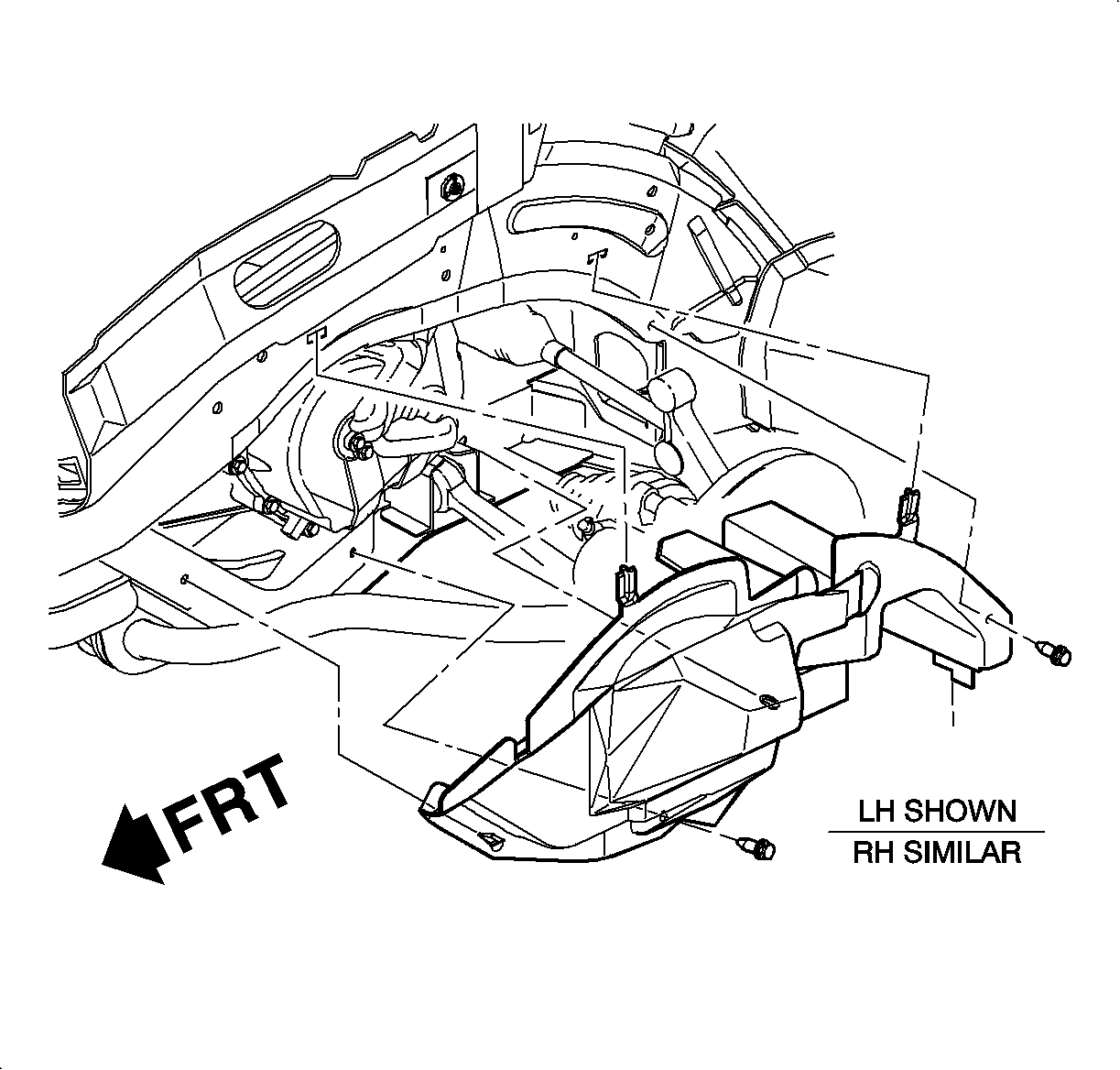
Important
Remove front section of splash shield first, then rear.
- Remove left side splash shield.
- Remove two push pins.
Important
If molded-in fasteners are damaged or broken, drill out with a 5/16 in. bit
and replace with a push pin.
- Remove lower shield to cradle molded-in fasteners at cradle by gently prying
at three fastener locations.
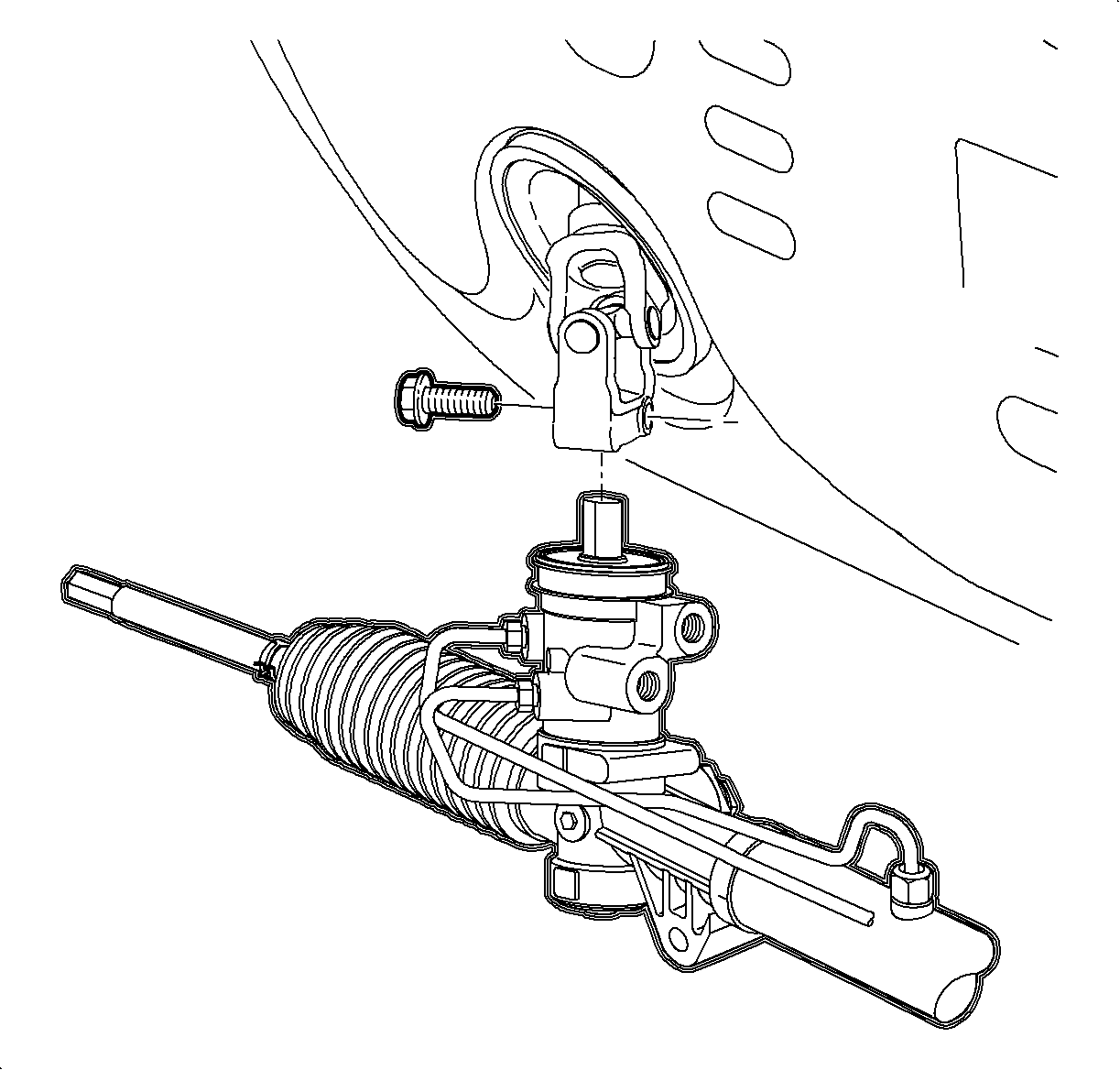
- Loosen intermediate steering shaft cover from steering gear and move up enough
to access pinch bolt.
- Remove pinch bolt.
- Place an approved drain container under pressure and return hoses at steering
gear.
- Remove power steering pump pressure and return hoses from steering gear
and allow system to drain.
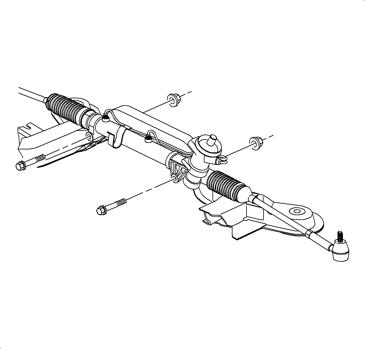
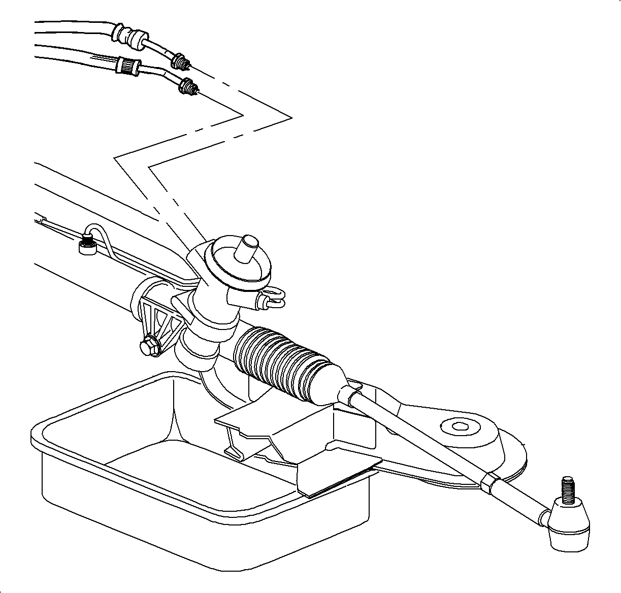
- Remove steering gear-to-frame fasteners and remove steering gear from vehicle
through left fender well.
- Place steering gear in vehicle.
- Install steering gear-to-frame bolts and new
nuts.
TightenTighten Steering Gear-to-Frame Fasteners 50 N·m (37 lbs ft).
Important
Use Loctite 242® Threadlocker (or equivalent) on thread of pinch bolt.
- Install intermediate shaft onto steering gear and torque the pinch bolt.
TightenTighten Intermediate Steering Shaft-to-Steering Gear Pinch Bolt 47 N·m
(35 lbs ft).
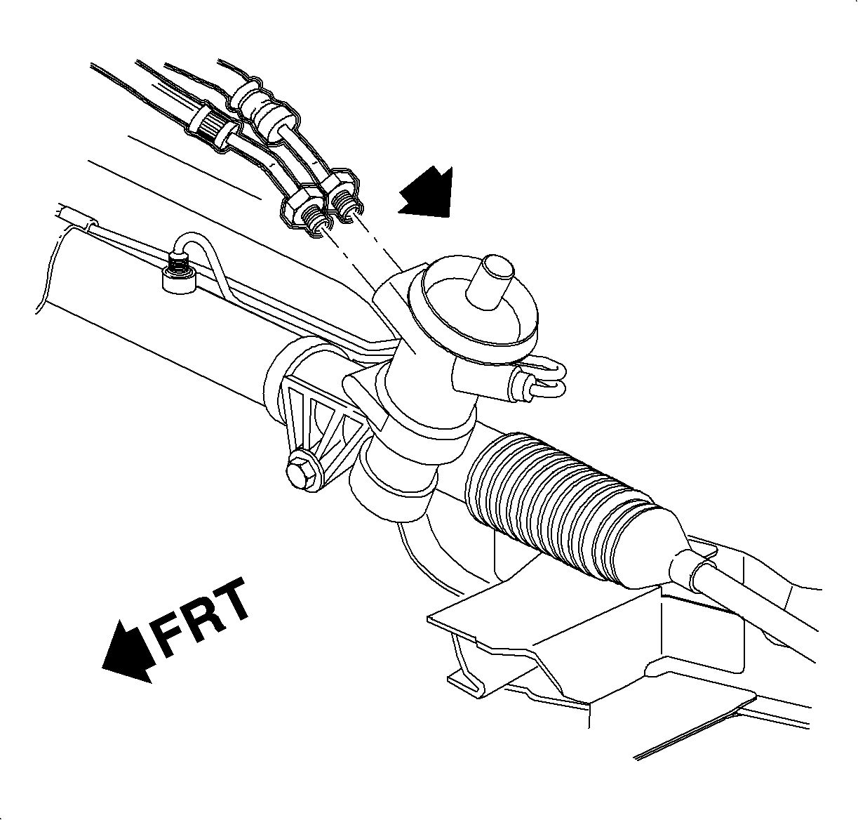
- Install power steering pressure and return hoses.
TightenTighten Power Steering Hoses-to-Steering Gear 27.5 N·m (20 lbs ft).
Important
Install rear section of splash shield first.
- Install left side splash shield.
- Install tabs in body cut-out.
Important
Make sure splash shield flaps are tucked in at body locations.
- Align molded-in shield fasteners with holes in cradle. Push straight in to install.
- Install push pins.
Important
Tie rod end threads must be thoroughly cleaned before tightening nut. Do not
lubricate any portion of the stud.
Important
Use new nut, torque retention of old nut may not be sufficient.
- Seat tie rod end into steering knuckle by using
J 44015
or equivalent.
TightenTighten Tie Rod Linkage Installer 45 N·m (36 lbs ft).
Important
This procedure requires
SA9140E
(or equivalent).
- Remove linkage installer and install new
tie rod
end nut.
TightenTighten Tie Rod-to-Steering Knuckle Nut 25 N·m (19 lbs ft)
+134°.
Important
Lower control arm ball stud threads should be thoroughly cleaned and lubricated
before installing and tightening nut.
- Tighten ball joint stud castle nut.
TightenTighten Ball Joint Stud Castle Nut 75 N·m (55 lbs ft).
Important
If necessary to rotate castle nut to align with the hole in stud, always tighten
the nut to align it; never loosen it. Install new cotter pin.
- Connect negative battery cable.
TightenTighten Battery Cable Bolts 17 N·m (13 lbs ft).
Notice
Before installing wheels, remove rust or corrosion from wheel mounting surfaces
and brake rotors/drums. Failure to do so can cause wheel nuts to loosen in service.
- Position wheel onto hub.
- Install wheel nuts and tighten in a crisscross pattern. Repeat tightening
pattern to make sure torque is correct.
TightenTighten Wheel Nuts 140 N·m (103 lbs ft).
- Set toe. Refer to
Wheel Alignment Specifications
in Wheel Alignment.
- Bleed power steering system. Refer to
Bleeding the Power Steering System
.