Compressor Replacement
Tools RequiredS8190A
Removal Procedure
Caution
Refer to Battery Disconnect Caution in Cautions and Notices.
Notice
When servicing the compressor, keep dirt and foreign material from getting on
or into the compressor parts and system. Clean tools and clean work area are important
for proper service. The compressor connections and the outside of the compressor should
be cleaned before any ON CAR repairs, or before removal of the compressor.
The parts must be kept clean at all times and any parts to be assembled should be
cleaned with a non-petroleum based solvent and dried with air. Use only lint free
cloths to wipe parts. Do not allow solvent to enter compressor or hoses.

- Disconnect
the negative battery cable.
- Recover the refrigerant using an approved refrigerant recovery system.
Measure the amount of oil lost during recovery and record.
Important
Verifying the purity of the refrigerant with a refrigerant purity identifier
before recovery is recommended.
Important
Steps 3 through 9 are only necessary if the vehicle is equipped with
a secondary air pump reaction system (AIR).
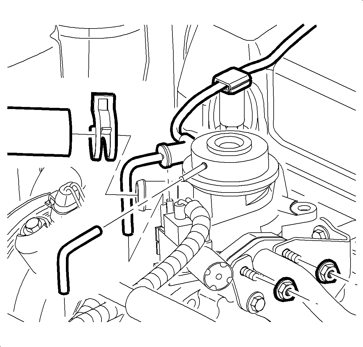
- Remove the nuts from the combination valve studs.
- Remove the air hose.
- Remove the vacuum source hose. There is no need to disconnect the internal
vacuum hose for this procedure.
- Remove the combination valve and gasket from
the rear air compressor bracket.
- Position the combination valve and gasket away from the A/C compressor
bracket.
- Remove the air pipe nuts from the exhaust manifold studs.
- Remove the air pipe.
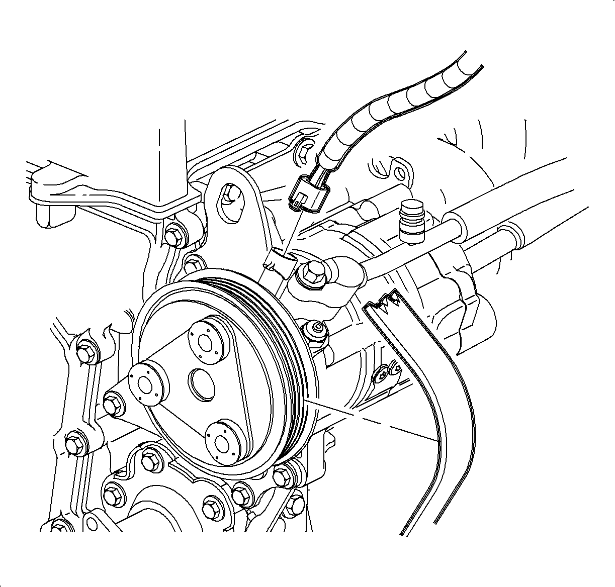
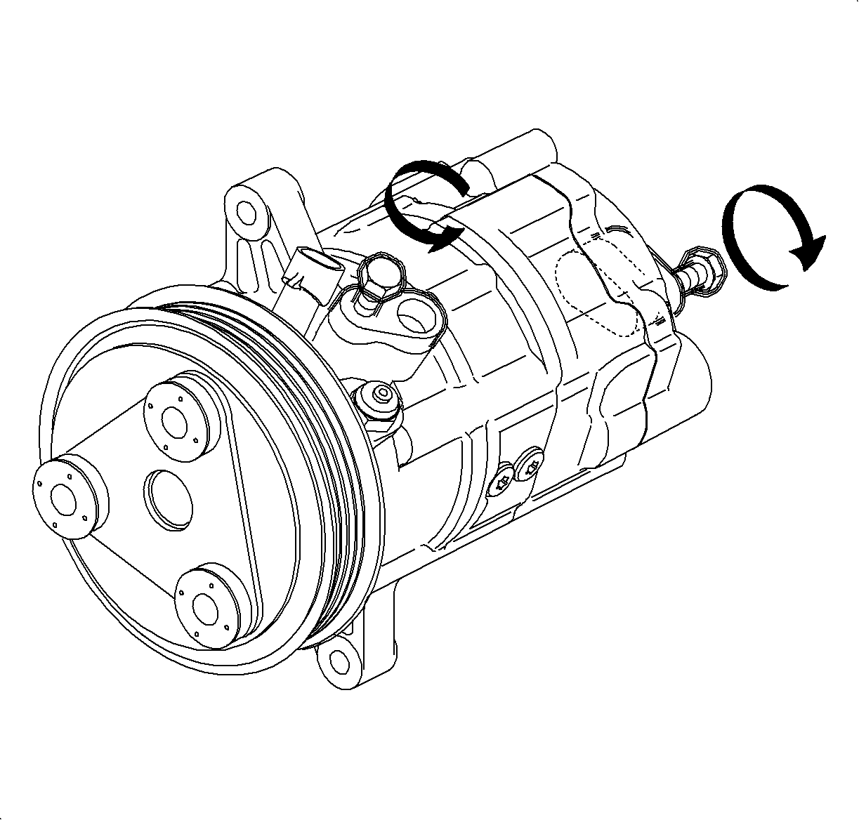
- Remove the accessory drive belt from the compressor
clutch pulley by rotating the belt tensioner clockwise using a 14 mm (9/16 in)
wrench. Snap-On tool S8190A or equivalent can be used.
- Disconnect the compressor clutch electrical connector.
Caution
Do not remove hoses or lines before system is fully discharged. System may be
under pressure and contact with R134a may cause personal injury.
- Disconnect the suction and the discharge
hoses at the compressor.
- Install plastic bags on the open end of the low and high side hoses.
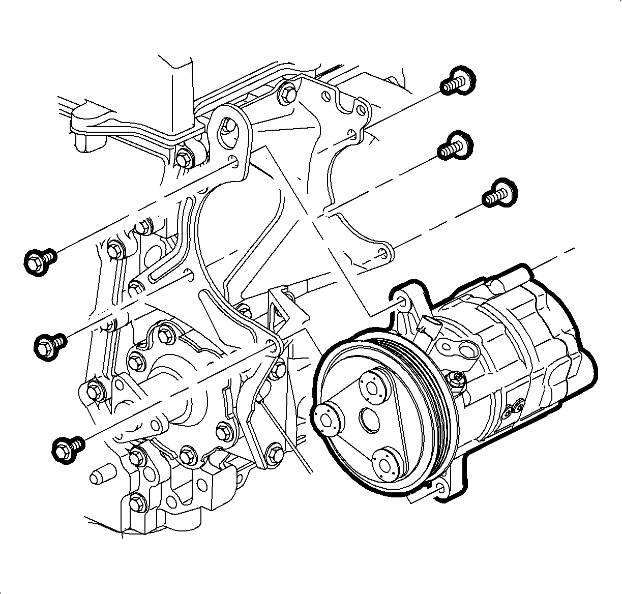
- Remove the rear compressor to bracket bolts.
- Remove the front compressor to bracket bolts.
Important
Keep the compressor level during removal to avoid any oil loss from the low
or high side ports.
- Remove the compressor.
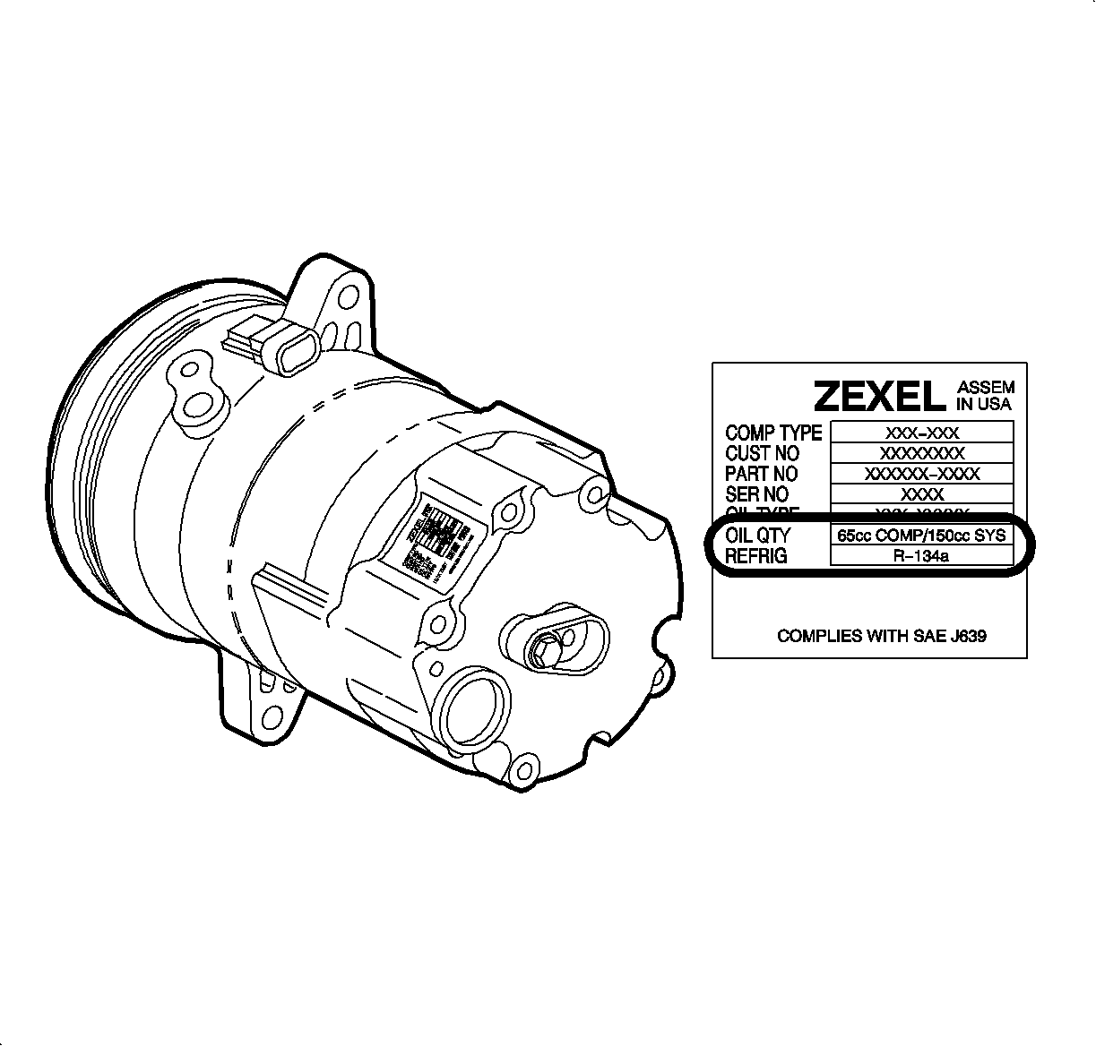
Oil Measurement
Important
PAG oil charge can be identified by locating the label on the rear of the A/C
compressor. The 65cc PAG oil charged service replacement A/C compressor will read
65cc COMP/150cc SYS (150cc oil charge in the total system for the model year serviced).
Improper quantity of oil charge in the system will degrade the performance.
- Remove the A/C compressor from the vehicle.
Notice
During oil removal procedure, condition of oil should be evaluated. Compressor
oil never breaks down unless something is wrong with the compressor or A/C system.
If one or more of the following conditions exist, replace compressor and receiver-dehydrator.
- Color of oil is dark brown or black
- There is a presence of foreign substances, metal fittings, etc. in oil
If receiver-dehydrator is not replaced damage to A/C compressor will occur.
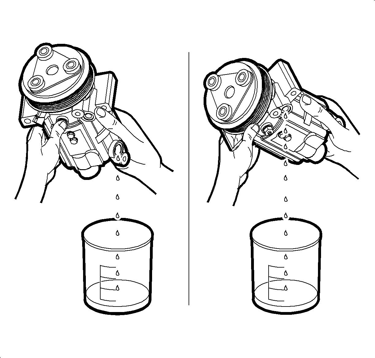
- Drain the oil into
a clean container.
- Position the A/C compressor to the drain from the high side port first.
- Move the A/C compressor to different positions to remove all the oil possible.
- Turn the A/C compressor over to drain the oil from the low side port.
- Rotate the A/C compressor drive plate in both directions to remove the
oil from the A/C compressor chambers.
- Stop the oil draining when the oil coming from the low and high side ports
becomes only drops.
- Measure and record the oil removed from the A/C compressor.
- Discard the removed oil, as all new replacement (service) A/C compressors
come installed with 65cc of Saturn PAG compressor oil.
- Place the new A/C compressor on a clean work
bench with the high and low side ports in an upright position.
- With the A/C compressor high and low side ports in an upright position,
slowly remove the high side cap retaining bolt to release the nitrogen (N2) charge.
- Remove the high and low side caps. Install the high and low side caps
on the A/C compressor removed from the vehicle, to prevent any oil from leaking out
when the A/C compressor is being shipped.
Important
Oil drained from the new A/C compressor can be installed if drained into a clean,
dry container.
- Install the oil drain adapters on the high and low side ports of the new A/C
compressor.
- Drain the oil from the new A/C compressor into a clean, dry container.
- Position the A/C compressor to drain from the high side port first.
- Move the A/C compressor to different positions to remove all the oil possible.
- Turn the A/C compressor over to drain the oil from the low side port.
- Rotate the A/C compressor drive plate in both directions to remove the
oil from the A/C compressor chambers.
- Stop the oil draining when the oil coming from the low and high side ports
becomes only drops.
- Measure and record the oil removed from the A/C compressor.
Important
Additional NEW Saturn PAG oil may be needed to obtain the amount of PAG oil
required for the next step.
- Add the recorded amount of oil drained from the removed A/C compressor, measurement
amount was obtained in previous steps, and the amount of oil lost during the recovery
process to the new A/C compressor.
- Install the A/C compressor into the vehicle.
Installation Procedure
Important
Keep the compressor level during installation to avoid any oil loss from the
low or high side ports.
- Install the compressor to the front bracket bolts. Finger tighten only.
Notice
Refer to Fastener Notice in Cautions and Notices.
- Install the compressor to the rear bracket bolts. Tighten the front and rear
bolts to specifications.
Tighten
- Tighten the A/C compressor front bolts-to-bracket to 49 N·m
(36 lb ft).
- Tighten the A/C compressor rear bolts-to-bracket to 25 N·m
(19 lb ft).
Notice
Use only Polyalkylene Glycol Synthetic Refrigerant Oil (PAG) for internal
circulation through the R-134a A/C system and only 525 viscosity mineral oil
on fitting threads and O-rings. If lubricants other than those specified are
used, compressor failure and/or fitting seizure may result.
Important
Do not lubricate the new slim line seal washer on the compressor side of the
suction hose. The slim line seal washer cannot be interchanged with a typical O-ring
in the A/C system. Use only suction line slim line O-rings as a replacement.
- Remove the plugs or plastic bags from the suction and discharge hoses.
- Install a new suction hose to the compressor slim line seal washer. Do
not lubricate.
- Lubricate the O-ring.
- Install the O-ring for the discharge hose to the compressor.
- Install the hoses to the compressor low and high side ports. Tighten the
bolts to the specifications.
Tighten
- Tighten the suction hose-to-compressor to 25 N·m (19 lb ft).
- Tighten the discharge hose-to-compressor to 25 N·m (19 lb ft).
- Connect the compressor clutch electrical connector.
- Install the accessory drive belt.
Notice
Make sure gaskets are installed correctly or a leak will occur. If gaskets are
removed from stubs, replace with new gaskets. Installation steps must be performed
in sequence.
Important
Steps 10 through 16 are only necessary if the vehicle is equipped with a secondary
air pump reaction system (AIR).
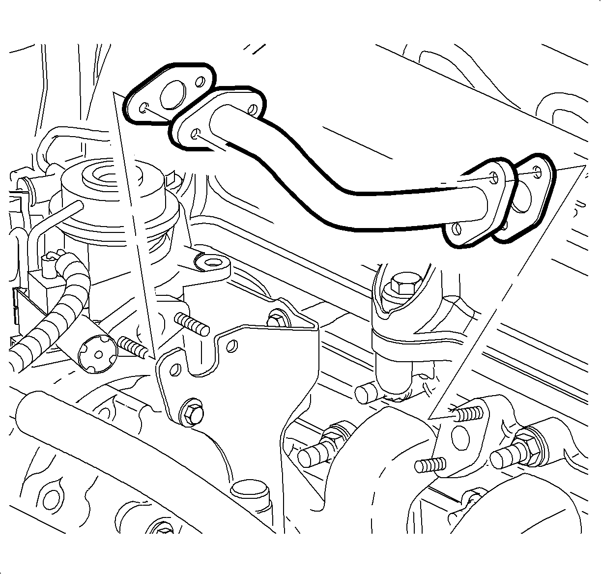
- Install the air pipe onto the exhaust manifold studs.
- Install the air pipe into the rear air compressor bracket slot.
- Install the combination valve studs into the rear air compressor bracket
through the air pipe flange holes.
- Install and tighten the nuts on the combination valve studs.
TightenTighten the air system combination valve nuts to 7 N·m (62 lb in).
- Install and tighten the nuts on the exhaust manifold
studs.
TightenTighten the air system pipe-to-exhaust manifold studs to 7 N·m
(62 lb in).
- Install the vacuum source hose.
- Install the air hose.
- Connect the negative battery cable.
TightenTighten the negative battery cable to 17 N·m (13 lb ft).
- Set the clock to the proper time.
- Evacuate, charge and leak test the A/C system.
- Run the A/C performance test.