Caution
Refer to Battery Disconnect Caution in Cautions and Notices.

- Raise the vehicle on a hoist. Refer to
Lifting and Jacking the Vehicle
in General Information.
- Remove the left front wheel and tire assembly.
- Remove the left wheelhouse splash shield.
- Drain the transaxle fluid.
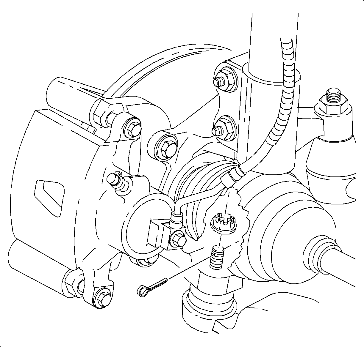
- Remove the cotter pin from the lower ball joint and discard ti. Loosen the nut
and back it off until the top of nut is even with the top of threads.
Notice
On ABS equipped vehicles, the outer CV joint has a speed sensor ring. Using
the incorrect tool or procedure to separate the control arm from the knuckle can damage
the ring, resulting in a loss of ABS operation.
Notice
Do not attempt to separate the joint using a wedge-type tool because seal may
be damaged.
- Separate the ball joint from the steering knuckle using the
SA9132S
and remove the nut.
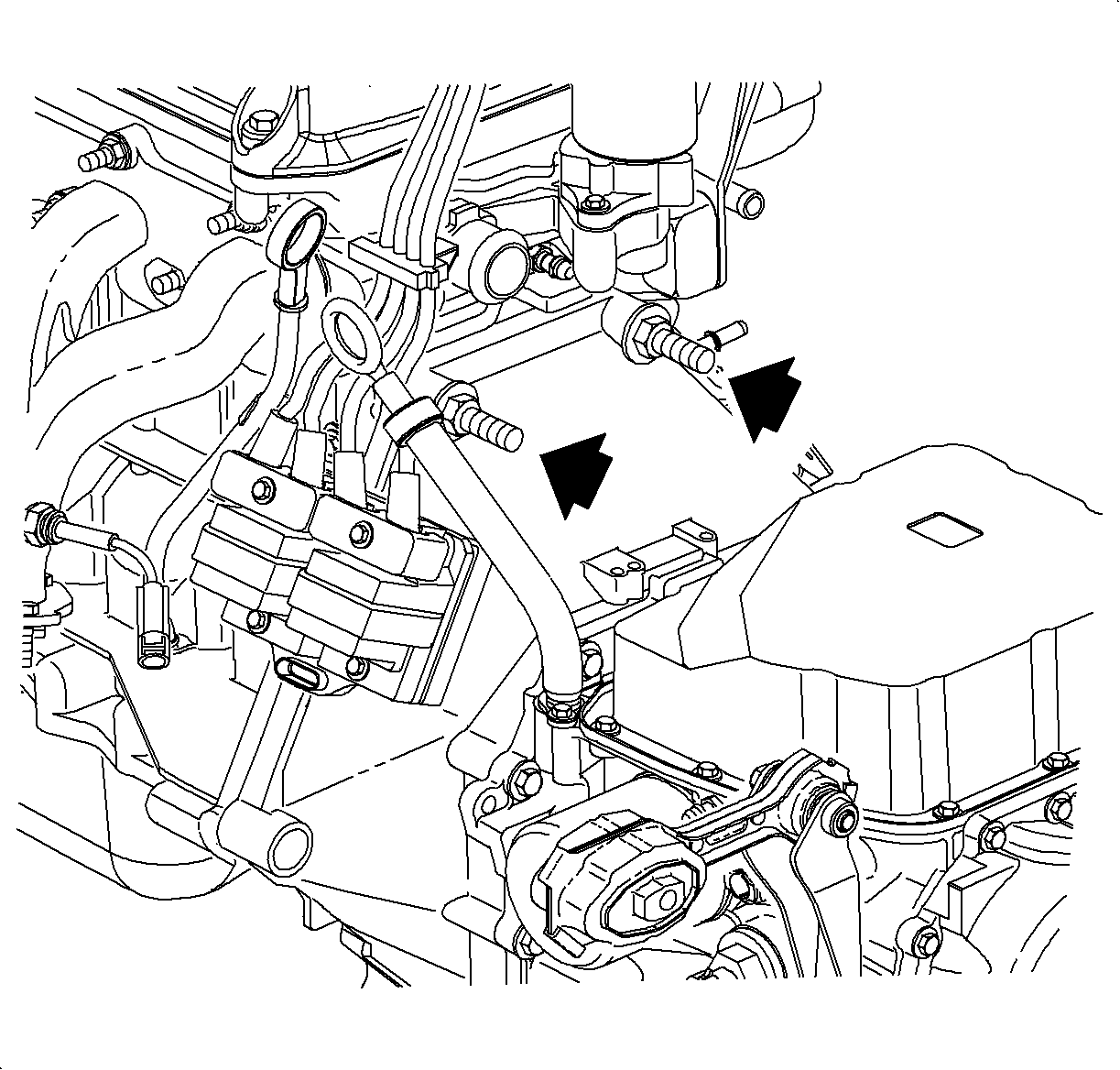
- Remove the bolt retaining the brake line bracket to the inner fender and
position the brake line to avoid interference.
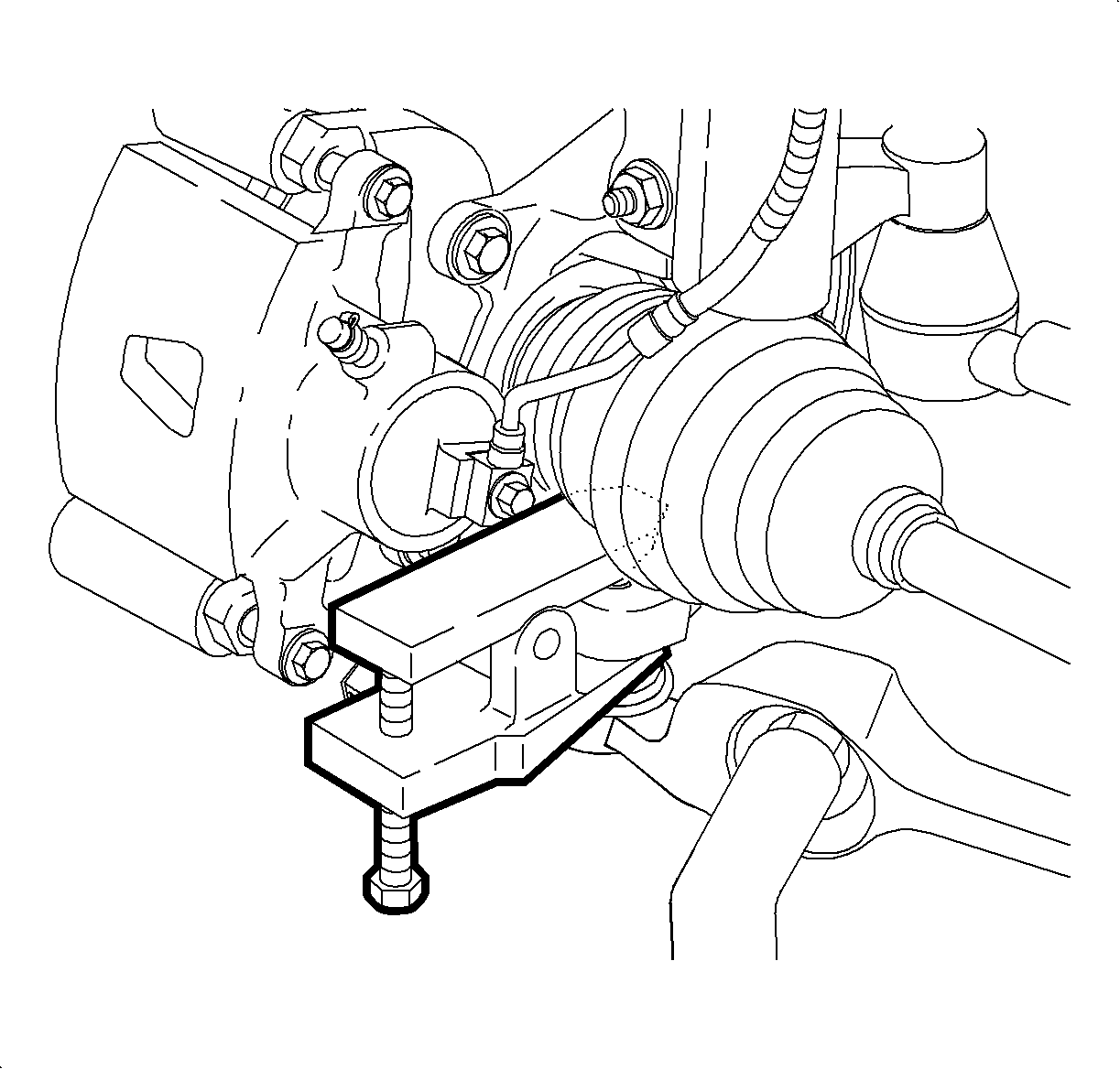
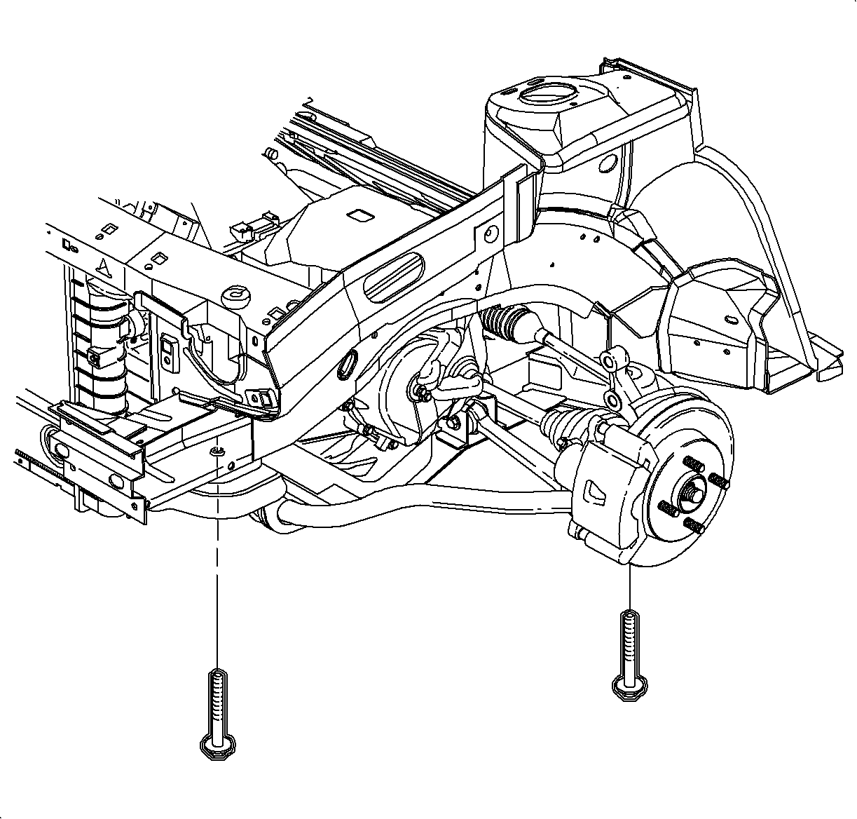
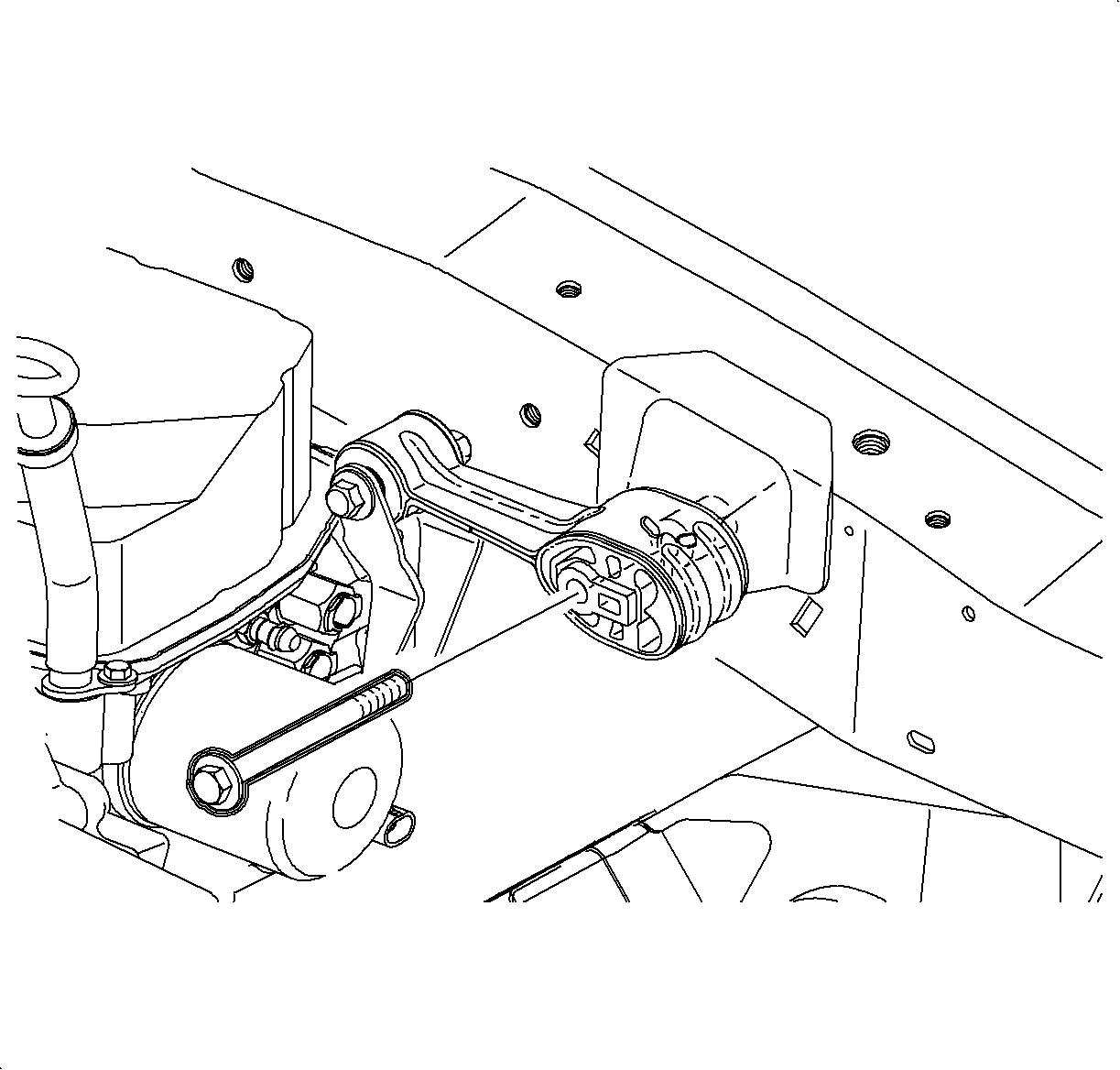
- Remove the transaxle mount-to-frame fastener.
- Place a screw type jack stand under the transaxle casing use a block of
wood between the stand and casing to unload the transaxle lower mount.
- Remove the 2 mount-to-transaxle fasteners.
- Loosen and back off on the 2 frame-to-body bolts. Do not remove the
bolts.
- Raise the powertrain enough to remove the mount from the vehicle.
- Lower the jack.
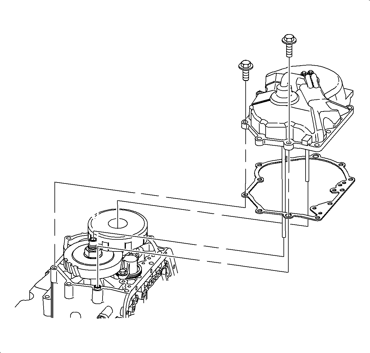
- Remove the end cover bolts.
Notice
Use care when removing end cover as the tubes can bend easily.
- Remove the end cover. Refer to
End Cover Replacement
. 1st design shown, 2nd design similar.
- If replacing the 1st gear assembly, refer to
1st Clutch, 1st Drive Gear and 1st Driven Gear Replacement (On-Vehicle)
.
- Clean the gasket surfaces and install the gasket on to the end cover dowel pins.
Install the end cover to the transaxle case. Insert the input and output shaft
tubes into the ends of the shafts and install cover. If the cover does not seat, rotate
the axle to help align the tubes with the bushings in the shafts. 1st design shown,
2nd design similar.
Notice
Refer to Fastener Notice in Cautions and Notices.
Important
Clean and lubricate the fasteners with Saturn Transaxle Fluid. Wipe off excess
fluid.
- Install the end cover to case bolts and tighten using the tightening sequence.
TightenTighten the end cover-to-case bolts to 28 N·m (21 lb ft).
- Install the bolt into the brake line bracket and tighten.
TightenTighten the brake line bracket-to-transaxle bolt to 5 N·m (44 lb in).
- Raise the powertrain up and install the transaxle mount.
- Install the 2 lower mount-to-transaxle fasteners.
TightenTighten the lower mount-to-transaxle bolts to 32 N·m (24 lb in).
- Tighten the 2 frame-to-body bolts.
TightenTighten the frame-to-body bolts to 210 N·m (155 lb in).
- Lower the powertrain completely.
- Install the transaxle lower mount-to-frame fastener.
TightenTighten the lower mount-to-frame nut to 48 N·m (35 lb in).
- Install the left wheelhouse splash shield.
- Clean and lubricate the ball joint threads.
Notice
Take care not to damage rubber boot when installing ball joint to knuckle.
- Position the ball joint into the steering knuckle.
- Install the nut to the lower ball joint and tighten.
TightenTighten the lower ball joint-to-steering knuckle nut to 75 N·m
(55 lb in).
- If necessary, after tightening, tighten the nut additionally to align
the slot in the nut with the cotterpin hole in the ball joint, and install the cotter
pin and bend the ends.
Notice
Before installing wheels, remove rust or corrosion from wheel mounting surfaces
and brake rotors/drums. Failure to do so can cause wheel nuts to loosen in service.
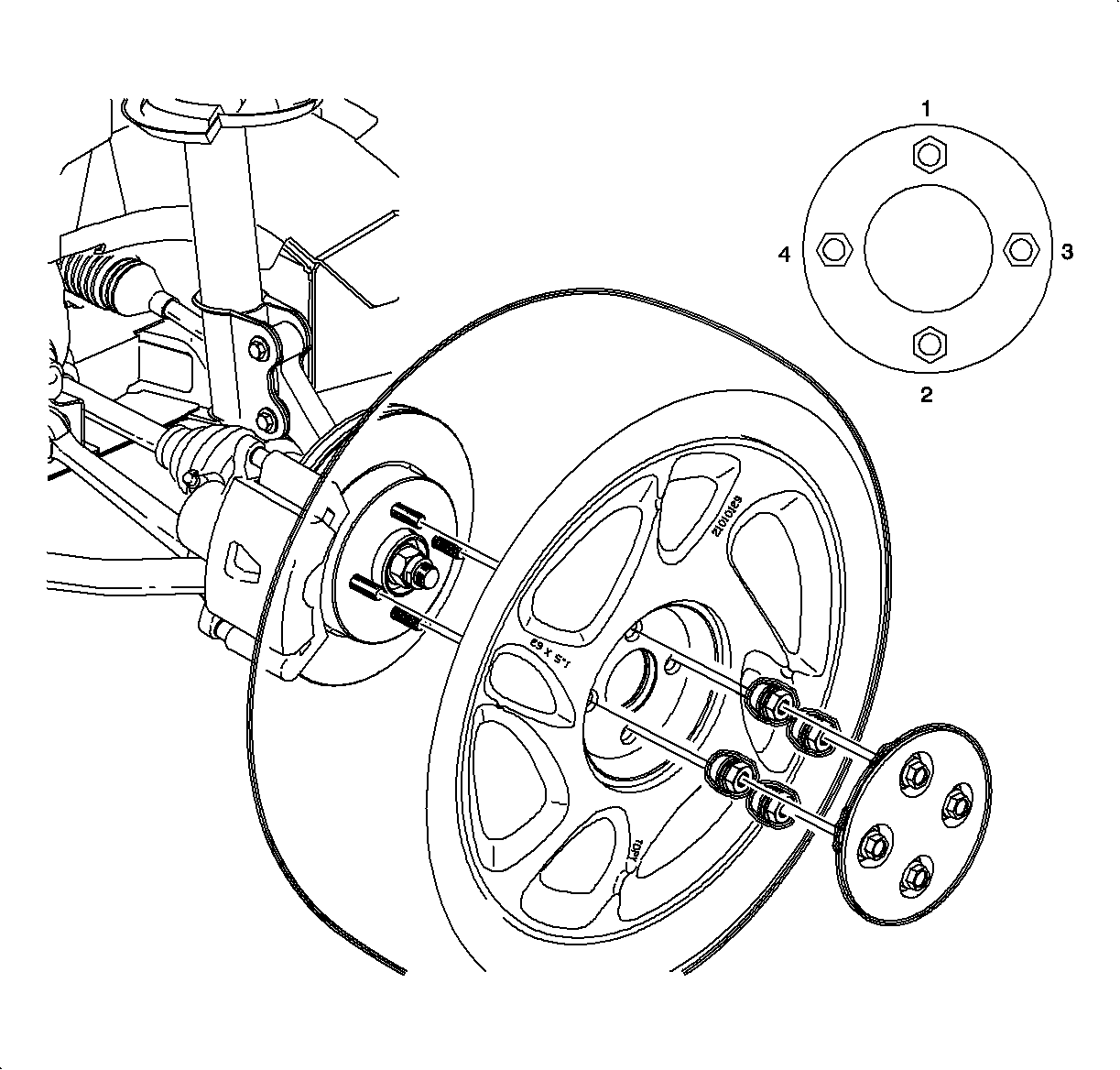
- Position the wheel onto the hub.
- Install the wheel nuts and tighten them in a crisscross pattern.
Repeat the tightening pattern to be sure torque is correct.
TightenTighten the wheel lug nuts to 104 N·m (103 lb in).
- Lower the vehicle from hoist.
- Fill the transaxle with fluid.
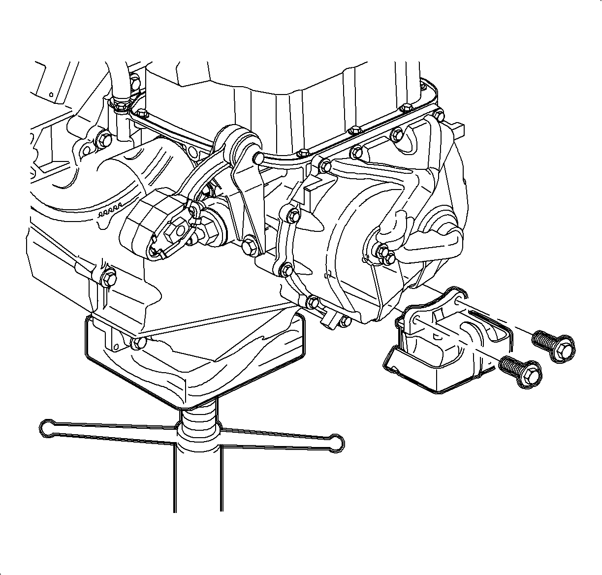
- Install the transaxle strut-to-midrail bracket fastener.
TightenTighten the transaxle strut-to-midrail bracket bolt to 70 N·m (52 lb in).
- Install the air
cleaner and duct assembly. Refer to
Air Cleaner Housing and Duct Assembly Replacement
.
- Verify the fluid level. Refer to
Transmission Fluid Checking Procedure
.